In light of new evidence, what might be behind the Casimir Effect?

In summary: The photons created by the base electrode will still cross the insulator and hit the upper electrode, but the photons will be absorbed and not cause any electrical current.I think this would be incredibly interesting to explore and determine for sure. But I'm not sure how to go about it.In summary, Moddel's experiment shows that virtual photons can have a real effect, potentially creating an electrical current from the quantum vacuum.
  • #1
peterbb
15
1
TL;DR Summary
A study published by Garret Moddel seemed to show that electrical energy can be extracted from what seems to be the quantum vacuum and produce steady current. Is it possible to simplify his model through a deeper understanding of the Casimir Effect. What kind of physics is really creating this force?
(note to mod: I changed the journal to a more reputable one that should fit the rules - please check if it's approved for you - thanks!)

Preface​

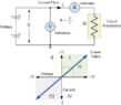
Some of you may know this but a little while ago Garret Moddel, a professor at Boulder Colorado University, published a paper that described an experiment he did where he was able to use a combination of a Casimir cavity and an extremely thin conductor-insulator-conductor combination to generate a steady supply of current, potentially from the quantum vacuum. He also seems to have accounted for a lot of potential errors that may have led to mis-readings.

symmetry-13-00517-g001.png


Really fascinating and interesting experiment. There's a fantastic video for those interested where he goes more in depth comparing different variations of quantum theory and they might explain it, but I'll give the basic overview here as I understand it quickly to give some preface to my question. Please note I am seriously not an expert in this at all and may be totally off. Reference the above picture.
  1. The Casimir Cavity/Optical Cavity (~30nm thick) essentially blocks all wavelengths > 30nm in the transparent dielectric (I know it's about harmonic resonance but let's just keep it simple for now).
  2. The upper electrode (palladium) is 2nm thick. The insulator below is also 2nm thick.
  3. According to Heisenberg's uncertainty principle, high energy quantum fluctuations in the form of photons can exist for a very short time. A particle travelling at the speed of light can exist therefore exist for a very small distance (in this case, 2nm is enough distance for a UV photon to cross, I believe - I might be off about this exactly).
  4. The upper electrode cannot support >30nm wavelengths due to the casimir cavity on top of it blocking them from coming through from above. As well, the electrode is too thin for them to appear within the conductor. Whereas the base electrode can create them because it's quite a bit thicker. This creates asymmetry across the insulator as more spectrum can be created in the base electrode versus the upper electrode.
  5. Wavelengths > 30nm "cross" the insulator from the base electrode and exciting electrons in the upper electrode.
  6. Assuming Moddel (if I understand correctly) puts forth this idea whereby a virtual photon can become real under a certain condition (related to frustrated total internal reflection), to account for the possibility that quantum fluctuations are virtual. Essentially, when a real photon is reflected internally, there is a virtual photon probability wave that emanates on the other side of the point of reflection, which goes outward and can collapse where it meets another thicker medium. This probability wave expands (I think similar to quantum tunnelling), and can be converted into a real photon. So his idea is that this "conversion" process might be happening at the boundary of the insulator and the upper electrode, where virtual quantum fluctuations are being "converted" to real photons.
  7. All of this creates an electrical circuit via the photoelectric effect.
(Note: I believe electrons are re-introduced into the upper electrode via quantum tunnelling from the base one but that's a bit beyond me)

My question, topic of discussion:​

So as far as I know, and I know very little, the casimir effect is essentially caused by the "pressure" of quantum fluctuation. This is all I can really find out about it without going really deep into the math which is beyond me (I am practicing!). But what exactly is pressure? I really tried to dig this up but couldn't really get to the bottom of it. In classical physics pressure is excitation of atoms and molecules smashing against something. Obviously classical physics doesn't really translate into the quantum world generally. But what is the equivalent explanation for virtual particles creating real effects?

As I understand it, quantum fluctuations were seen as being virtual for the longest time. Yet, the Casimir effect shows that they do indeed have a real effect. How can something virtual have a real effect? I have been trying to follow the logic of how exactly the mechanism of this works. How is something virtual "translated" into a real effect?

Is it possible that it isn't virtual at all? Maybe the force is symmetrical everywhere and in everything in all directions such that the net effect is 0 on everything from a practical perspective, and so we just call it virtual? Since in nature it's incredibly rare for quantum fluctuation asymmetry to be created spontaneously, we just assume it's virtual? If two people push on a box from both sides, they equalise it and so there is net 0 effect. Does that make their pushing virtual? I would say not.

Nevertheless, I wonder whether that's actually the case. Is it possible that quantum fluctuation photons are actually real photons?

If this were true, then we could create the following experiment. Basically we remove altogether the insulator and metal at the bottom. Now we have just a casimir cavity except using an insulator instead of a vacuum. The difference is, in this casimir cavity, the base plate is extremely thin. Let's say 20nm. This way anything above 20nm wavelength won't be created within it, therefore creating asymmetry. I haven't looked it up, but is it possible what I'm about to say has never been observed because the parallel plates were always quite big?
Screenshot 2023-07-29 at 10.54.52.jpg

If the conductor is too thick, there won't be asymmetry in the high-energy photon range. But if it's 20mm, maybe these photons would excite electrons in the conductor via the photoelectric effect. But where would the electrons go? They would need an opposite charge to create current. Maybe, maybe, nobody ever bothered to create something like this, let alone measure it. Because how do we measure it? There's no circuit like there is in Garret's experiment.

What if we can use a P-N junction with two of these to create current similar to how solar panels work:

Screenshot 2023-07-29 at 10.55.50.jpg


I'm 99% sure this is just fantasy and represents my very very little knowledge on the subject. But the thing for me is that I don't really know why it won't work, because I don't understand how the casimir force is actually being created. And explanations I've found have left me unsatisfied. What explains Moddel's findings while still being aligned with the idea of it being virtual? The question ultimately for me is what exactly is pushing the conductors together? If photons are real enough to create current in Moddel's experiment, real enough to push two plates together, yet still not real, what would prevent them from creating current in this one?

To anyone with the patience to give this some thought and reply - thank you!
 
Physics news on Phys.org
  • #2
peterbb said:
generate a steady supply of current, potentially from the quantum vacuum
Where specifically in the paper does it say this? Basically you're saying that the device gives energy output without any energy input, indefinitely. Where in the paper is this claim made?
 
  • Like
Likes vanhees71 and Lord Jestocost
  • #3
peterbb said:
Please note I am seriously not an expert in this at all and may be totally off.
And given that, you should not be engaging in the kind of speculation that occupies the "My question, topic of discussion" part of your post. You should first get very clear about (a) the actual facts of the experiment (which I asked about in post #2) and (b) the actual best current theory we have about such experiments (which is much more nuanced and complex than the simplistic picture you give).
 
  • Like
Likes Dale
  • #4
  • #5
Thanks for your reply, Peter!

PeterDonis said:
Where specifically in the paper does it say this? Basically you're saying that the device gives energy output without any energy input, indefinitely. Where in the paper is this claim made?

It seems to be the case yes. Here is the portion of the text and the attached figure:

In addition to the changes in resistance reported here, a small anomalous offset current and voltage were observed in the Casimir photoinjector devices. This can be seen in Fig. 5 [[[[ picture below ]]]], which shows the low voltage range of the devices presented in Fig. 3(a). With the base electrode as ground, a positive current flows from the upper electrode to the base electrode at 0 V. If we assume that ZPFs cannot be the power source, an external voltage source would be needed. As described in the Supplemental Material [39], we carried out extensive experiments aimed at eliminating this offset, including developing an improved method for measuring low-current electrical characteristics, recalibrating instrumentation, producing temperature gradients to check for thermoelectric effects, making arrays to check that the voltage and current offsets scaled with the respective number of devices in series and in parallel (they did), investigating whether the voltage and current offsets might be transient and possibly a result of hysteresis during measurement (the currents are stable over a period of hours with no externally supplied power), and making sure that the devices are blocked completely from any stray light during measurement. Thus far, we have been unsuccessful in finding an artifact that would explain the anomaly. These offsets are small compared with the voltage and current ranges used to measure the differential conductance values and therefore do not affect those measurements. We describe these currents and voltages in more detail in a separate publication [49].

1690668341989.png


(b) the actual best current theory we have about such experiments (which is much more nuanced and complex than the simplistic picture you give).

Yes I'm aware that my picture is simplistic, which is why I'm not claiming that it works but wondering why it wouldn't in order to further my understanding of QM. My question is, given that in the above paper, there seems to be power generation, why wouldn't it be the case that a simple Casimir cavity with an ultra-thin conductor would not produce the same kind of photoinjection effect as in the paper?

I have no idea which theory of QM would support this, which is why I'm putting the question forward. I do appreciate that QM is counter-intuitive. It would also be cool I think to start a conversation and see how the bright minds here can maybe put their heads together and see what theory(s) fit with these findings.

Thank you for the links, I will read all of them. 👍
 
  • #6
peterbb said:
Here is the portion of the text and the attached figure
If the voltage between the upper electrode and the base is zero volts, then zero energy is being transferred by the observed current. This is already known to be the case for other materials, such as superconductors, in which a nonzero current can be sustained indefinitely with no energy input--but which also transfers no energy.

I don't know if anyone has investigated possible similarities between the device described in this experiment and superconductors, but that would seem to me to be an avenue that should be explored.
 
  • #7
PeterDonis said:
If the voltage between the upper electrode and the base is zero volts, then zero energy is being transferred by the observed current. This is already known to be the case for other materials, such as superconductors, in which a nonzero current can be sustained indefinitely with no energy input--but which also transfers no energy.

I don't know if anyone has investigated possible similarities between the device described in this experiment and superconductors, but that would seem to me to be an avenue that should be explored.
I don't think the X axis on the graph is showing the voltage output of the device (between the upper electrode and base), rather it's describing the voltage being applied to "counteract" the device. So when 0V is applied externally to it, the current flowing through the circuit is ~80nA. You have to apply 0.07mV against the device to make the current drop to 0. This implies that the device itself is generating power (kind of like pushing against a battery is how I imagine it).
 
  • #8
peterbb said:
I don't think the X axis on the graph is showing the voltage output of the device (between the upper electrode and base), rather it's describing the voltage being applied to "counteract" the device.
I don't know what you mean by this. The voltage is being measured, not applied; it is the measured voltage between the upper and the base electrode. See the "Measurement circuit" shown in Fig. 1.
 
  • #9
PeterDonis said:
the device gives energy output without any energy input
Btw, "without energy input" is clearly not the case in the experiment described in the paper: current is produced by "illumination" of the upper electrode, i.e., by photoemission. The illumination is an obvious energy input.
 
  • Like
Likes Dale
  • #10
PeterDonis said:
I don't know what you mean by this. The voltage is being measured, not applied; it is the measured voltage between the upper and the base electrode. See the "Measurement circuit" shown in Fig. 1.

It's a current-voltage characteristic graph, I believe the measurement circuit is just showing where the device is located. Here is an excerpt from wikipedia on a current-voltage characteristic:

Active vs passive: Devices which have I–V curves which are limited to the first and third quadrants of the I–V plane, passing through the origin, are passive components (loads), that consume electric power from the circuit. Examples are resistors and electric motors. Conventional current always flows through these devices in the direction of the electric field, from the positive voltage terminal to the negative, so the charges lose potential energy in the device, which is converted to heat or some other form of energy.

In contrast, devices with I–V curves which pass through the second or fourth quadrants are active components, power sources, which can produce electric power. Examples are batteries and generators. When it is operating in the second or fourth quadrant, current is forced to flow through the device from the negative to the positive voltage terminal, against the opposing force of the electric field, so the electric charges are gaining potential energy. Thus the device is converting some other form of energy into electric energy.
1690672815768.png
 
  • #11
PeterDonis said:
Btw, "without energy input" is clearly not the case in the experiment described in the paper: current is produced by "illumination" of the upper electrode, i.e., by photoemission. The illumination is an obvious energy input.
Are you referring here to ambient illumination, e.g. of the room?
 
  • #12
peterbb said:
Are you referring here to ambient illumination, e.g. of the room?
No. The paper explicitly says that the upper electrode is illuminated to produce what it calls "hot carriers". In other words, it is making use of the photoelectric effect.
 
  • #13
peterbb said:
I believe the measurement circuit is just showing where the device is located.
Again I don't know what you mean. The measurement circuit in Fig. 1 explictly shows an electrical ground at the base electrode and an arrow giving the direction of positive current.
 
  • #14
peterbb said:
It's a current-voltage characteristic graph
It shares some aspects of one, but I'm not sure it's that simple.

Even with the simple picture given in the Wikipedia article, however, it is evident that points anywhere on the axes (which the zero voltage point described in the paper is) have zero power--they are neither producing nor consuming power. Which is consistent with what I said in my previous post, that zero energy is being transferred.
 
  • #15
PeterDonis said:
No. The paper explicitly says that the upper electrode is illuminated to produce what it calls "hot carriers". In other words, it is making use of the photoelectric effect.
Oh yes, well that's his theory on what seems most likely to be producing the energy. That essentially the casimir cavity creates an imbalance of quantum fluctuations, and the repression of certain wavelengths on one side of the insulator creates what I might describe as a quantum fluctuation asymmetry, but only virtual asymmetry. The boundary between the insulator and upper electrode 'captures' or converts virtual photons to real photons in a way similar to frustrated total internal reflection (essentially tunnelling, as I understand it). Leading then to the photoelectric effect.

The question that comes to me is like, what theory supports this idea? The part about quantum fluctuations converting to real photons. And which theories don't? And what other configurations can one make leveraging this phenomena to essentially get real photons out of virtual quantum fluctuations. It might be used for many applications if we can pin it down more. Probably something I'll understand a bit more once I read through all the links you sent me!
 
  • Skeptical
Likes Motore
  • #16
peterbb said:
that's his theory on what seems most likely to be producing the energy
Not if his theory claims that the energy is coming from quantum "zero point energy", i.e., from nowhere. If the energy is coming from the incoming light that is inducing the photoelectric effect, then it's not coming from nowhere.

In any case, as I have already pointed out, at zero voltage there is no energy being produced.

The paper itself does not give enough information for me to tell what specific theoretical model he is using. However, it does not seem to me that he is taking into account the obvious items that I have just pointed out above. That makes me skeptical.

peterbb said:
quantum fluctuations converting to real photons
Is, at best, an oversimplified heuristic description of some kinds of processes (for example, look up "superradiance") that quantum field theory does indeed predict--but none of them involve energy coming from quantum "zero point energy".
 
  • #17
peterbb said:
what theory supports this idea?
As far as I can tell, this author's ideas are not supported by mainstream quantum field theory. I think he is well aware of that and is trying to push a particular line of research in the hope that some other physicists will pay attention and his ideas will get some traction. AFAIK he has not had any particular success at that so far.
 
  • #18
peterbb said:
As I understand it, quantum fluctuations were seen as being virtual for the longest time. Yet, the Casimir effect shows that they do indeed have a real effect. How can something virtual have a real effect? I have been trying to follow the logic of how exactly the mechanism of this works. How is something virtual "translated" into a real effect?
Perhaps a metaphor would help. Suppose that somebody owns you money. This means that you have virtual money, not real money. But it can have real effects.

However, it has to be said that quantum fluctuations are not virtual. They are real. Casimir effect depends on quantum fluctuations, not on anything virtual.
 
  • #19
Demystifier said:
Casimir effect depends on quantum fluctuations, not on anything virtual.
The Casimir effect is certainly real, but "quantum fluctuations" can be a misleading term to describe what is going on. That is why I referenced in post #4 the Insights articles on that topic that address many common misconceptions associated with that term, and with the term "virtual particles".
 
  • #20
PeterDonis said:
The Casimir effect is certainly real, but "quantum fluctuations" can be a misleading term to describe what is going on.
It can be misleading if one does not know what "quantum fluctuations" are. But on a more serious level, I don't think that one can explain Casimir effect without quantum fluctuations (understood properly).
 
  • #21
Demystifier said:
quantum fluctuations (understood properly)
My comment was not about the underlying mathematical theory. It was simply that the ordinary language term "quantum fluctuations" might not be the best term to use as a heuristic description of that theory. But of course once you've pointed to the actual math that the term represents, you can dispense with the term itself and avoid all confusion.
 
  • Like
Likes mattt
  • #22
PeterDonis said:
ordinary language term "quantum fluctuations" might not be the best term to use as a heuristic description of that theory.
I can agree with that. What's your favored heuristic description of Casimir effect?
 
  • #23
Demystifier said:
What's your favored heuristic description of Casimir effect?
That the ground state energy inside the Casimir cavity is lower than the ground state energy outside.
 
  • Like
Likes Lord Jestocost
  • #24
PeterDonis said:
That the ground state energy inside the Casimir cavity is lower than the ground state energy outside.
Do you have a good a heuristic argument explaining why it is lower?
 
  • Like
Likes peterbb
  • #25
PeterDonis said:
Again I don't know what you mean. The measurement circuit in Fig. 1 explictly shows an electrical ground at the base electrode and an arrow giving the direction of positive current.

I think this is a really good pre-discussion topic because I-V curves can be a bit counter-intuitive. We definitely do need to be clear about the findings before we can discuss anything else, so let's go into the circuitry involved.

The paper considers the device under investigation from a resistance-measuring perspective, treating it as a resistor. To test a resistor, one usually applies a voltage source to it and plots the resultant current against this applied voltage. The following standard measurement circuit for testing a resistor serves as a good example:

1690707784567.png

source

Page 4 in the supplementary material of the paper talks more in detail about the electrical measurements and mentioned that they used four point probe configuration. This is what they are referring to by "measurement circuit" in Fig 1. Here is a video describing why this technique is necessary for tiny values (to negate the small effects of ammeter/voltmeter).

Below is the standard measurement circuit for a I-V curve using the four point probe technique. Also note that the voltage is being applied from the measurement circuit itself, in this case via a power supply. Measurements of current are being plotted based on voltage (changing the power supply).

1690707488767.png

(note that in the case of the device in question there is also a ground added)

When using I-V curves to measure a resistor, the line is expected to pass through the origin (V=0, A=0). However, when it doesn't pass through the origin, you get an X-intercept and Y-intercept:
  • The "open-circuit voltage" (Voc) (the voltage when no current is flowing I=0)
  • The "short-circuit current" (Isc), (the current that flows when there's no voltage drop across the device V=0).
This is because the device is generating the electrical power rather than an external voltage source driving the current.

It might be counter-intuitive that a voltmeter can read V=0 while current is running through it, but keep in mind this is because it's a short-circuit condition. In a short-circuit condition, the voltmeter will read 0 simply because all of the current is taking the path of no resistance, bypassing the voltmeter. Although it might seem that if V=0, then P=VI implies there's no energy, this isn't correct. Consider a battery. Short-circuit a battery and place a voltmeter in parallel and it will drop to 0. Doesn't mean the battery doesn't produce energy. The actual power generation is demonstrated by the curve of the IV graph passing through the 2nd quadrant.

Regarding the superconductor phenomena: It's my understanding that what you are referring to is due to the fact that superconductors have literally 0 resistance, allowing current to flow continuously at V=0. This is a different phenomena because with superconductors it is only observed at V=0 (analogy is a frictionless ball going in circles indefinitely), whereas the I-V curve of the device here not only has positive current at 0V, but has positive current from -0.07mV to 0. These I-V points are also continuous at each respective point as well over time. They don't drop over time like residual current would. It looks like this aspect is discussed more in the supplementary material.

1690709496763.png
 

Attachments

  • 1690707482221.png
    1690707482221.png
    1.7 KB · Views: 45
  • 1690705610859.png
    1690705610859.png
    6.1 KB · Views: 42
Last edited:
  • #26
PeterDonis said:
The paper itself does not give enough information for me to tell what specific theoretical model he is using. However, it does not seem to me that he is taking into account the obvious items that I have just pointed out above. That makes me skeptical.

Is, at best, an oversimplified heuristic description of some kinds of processes (for example, look up "superradiance") that quantum field theory does indeed predict--but none of them involve energy coming from quantum "zero point energy".

Skeptical - understandably so!

The paper doesn't go into theory because that's beyond the scope of it, as I understand it. It's merely a presentation of evidence, and we can use it to see test our theories against, which is why I'm interested in having the conversation here.

In the paper all reasonable possible external energy sources that could have been interfering with the measurements that are not zero-point are quite thoroughly accounted for and summarised above Fig 5 in the paper (the block a few replies ago).

In the video I posted in the OP, he also explains how he got the hunch for it. The impression I got was he was running with a theory but not married to it. It just happened to produce something. He also goes through a few theoretical models (standard model, stochastic electrodynamics, thermal model) in this video explaining the perspective they give regarding potential violate of the laws of thermodynamics (some do, some don't). But I want to bring the conversation here to more deeply understand what's happening at the quantum level in terms of what's actually creating this effect.

But yes of course one should be thorough in analysing this kind of stuff because there is always room for error! We should definitely pick it apart, but also understand it thoroughly so we're not skimming over important information, and also potentially missing something that can be an important discovery.
 
  • #27
This sounds a lot like perpetual motion. A lot.
No, I haven't watched the video. That is not a scientific source. Waste of my time.
The Casimir effect has nothing to do with vacuum energy and everything to do with boundary conditions.
There are not multiple theories of quantum mechanics. There is just quantum mechanics.
As perpetual motion machine go, this is the worst one I have ever seen. You put an unspecified amount of energy in and get an unspecified amount of energy out. Woo hoo!]

At least it puts the woo in woo hoo.

I think for this thread to go anywhere, it will need much better focus.
 
  • #28
Demystifier said:
Do you have a good a heuristic argument explaining why it is lower?
The presence of the conductors at the boundary of the cavity restricts the quantum field modes that are available inside the cavity, as compared to a free vacuum with no restriction on available modes. The fewer modes that are available, the lower the ground state energy of the vacuum.
 
  • #29
peterbb said:
In the paper all reasonable possible external energy sources that could have been interfering with the measurements that are not zero-point are quite thoroughly accounted for
This is true, but irrelevant. The claim is that energy is being output at zero voltage with no energy input. As I have already pointed out, multiple times now, both halves of that claim are false: there is no energy output at zero voltage (that's what zero voltage means), and there is energy input to the device at all voltages, because light is shining on at least one electrode. Nothing in the discussion of how other possible "interferences" were eliminated changes that.
 
  • #30
PeterDonis said:
This is true, but irrelevant. The claim is that energy is being output at zero voltage with no energy input. As I have already pointed out, multiple times now, both halves of that claim are false: there is no energy output at zero voltage (that's what zero voltage means), and there is energy input to the device at all voltages, because light is shining on at least one electrode. Nothing in the discussion of how other possible "interferences" were eliminated changes that.

It's good that you bring this up because it brings the opportunity for clarity:

Firstly,

There is no "light" shining on the device. The photo-injection and photoelectric effect you mentioned earlier is the basis of the energy coming from photons via quantum fluctuations in the electromagnetic field. This is all explained quite clearly in the first and second paragraph. With all due respect, I really get a strong impression you're skimming the article and picking out random bits, because this is explained quite clearly. I'd like to have an insightful conversation with you because I know you have knowledge but it doesn't work if you're literally not even reading the article.

Second,

This is a IV curve plotted against an externally applied voltage, and when the voltage is -0.07mv, the current stops. You can even ignore the V=0 point, due to the fact that on both sides of the graph where V>0 and V<0, there are points that show a positive current (really the negative is the only meaningful one, because a resistor would still be plotted on the positive side).

Furthermore, the X-intercept (V=0.08mv, I=0) is just as important as the Y intercept where (V=0, I=0.80nA). I'm not sure if you read my explanation on how four point probe IV curves work, because I wrote a pretty in-depth explanation there.

I don't claim to know anything that's going on at the quantum level, but the electrical stuff I can definitely speak to with a fair amount of confidence. You can actually do a power calculation from a linear IV curve as follows to calculate its peak energy:

The "open-circuit voltage" (Voc) = 0.07mV (<--- external voltage required to "stop" the current from flowing)
The "short-circuit current" (Isc) = 80nA (<--- current that flows in a short circuit condition)

Using a simple P=IV calculation (which does apply in this situation): 0.07mV * 80nA = 5.25 picowatts

And this is for a device that's 300nm x 250nm, assuming linear scaling that's roughly 65W/m^2
 

Attachments

  • Screenshot 2023-07-30 at 20.18.11.jpg
    Screenshot 2023-07-30 at 20.18.11.jpg
    23.5 KB · Views: 46
  • #31
"Our basic MIM device consists of a thin metal upper electrode, a thin insulator, and a thicker metal lower electrode. Illumination of the upper electrode
metal produces hot carriers,
 
  • #32
peterbb said:
There is no "light" shining on the device.
Yes, there is. From the lower left-hand column of the first page:

Photoinjection occurs when electromagnetic radiation incident on an absorber excites hot charge carriers...

"Electromagnetic radiation incident on an absorber" means coming from the outside, i.e., from light shining on the absorber. If there is no light shining, there is no incident radiation.

From the top of the right-hand column of the first page:

Illumination of the upper electrode metal produces hot carriers...

Unless there is a light shining on the metal, there is no "illumination".
 
  • #33
peterbb said:
This is a IV curve plotted against an externally applied voltage
Where in the paper does it say there is an externally applied voltage? Be specific.
 
  • #34
Ah okay I see where I can clarify here. Yes, you're right. There is light, in that sense. However, the "light" is coming from ZPF (zero point fluctuations), that's the whole point! The paper is making the point that the device seems to be internally illuminated via ZPF as a result of placing attaching a Casimir cavity to it.

Due to the all the other reasonable possible sources being ruled out, it seems logical to conclude that ZPFs are likely responsible for the illumination.

First two sentences of the abstract:

The differential conductance of metal-insulator-metal devices increases when they are joined with Casimir cavities. An imbalance in injection of hot charge carriers from each side of the insulator is increased with thinner cavities that suppress more quantum vacuum modes.

^ Here they are talking about the hot charge carriers increasing with thinner cavities, due to the Casimir effect suppressing more vacuum modes. That's your light source.

cont'd abstract:

The result is an observed increase in conductance. Additional conductance changes, with insulator thickness and other device parameters, are consistent with an imbalance-induced injection of hot carriers. In addition to the conductance changes, we observe anomalous offsets in the current and voltage. We interpret the conductance changes in terms of a 𝚫E𝚫t uncertainty principle-like limit to the injection of hot carriers from zero-point fluctuations.

PeterDonis said:
Where in the paper does it say there is an externally applied voltage? Be specific.

Repeating from my my previous post: It's in the paper's supplementary material. Page 4. Second sentence. It mentions the name of configuration they used to assess the resistance of the device. The technique is called the four point probe technique. If you google this you will see this technique always has a power supply attached to it on the outer two probes. That power supply is needed in order to generate the I-V curve. Vary the power supply and check voltage, plot, repeat, etc.
 
Last edited:
  • #35
peterbb said:
the "light" is coming from ZPF (zero point fluctuations)
That's not what the specific passages I quoted say. They say there is an external light source.

peterbb said:
this technique always has a power supply attached to it on the outer two probes. That power supply is needed in order to generate the I-V curve.
So that means there is another external source of energy, namely, the power supply.
 
  • Like
Likes hutchphd

Similar threads

Replies
9
Views
1K
Replies
10
Views
1K
Replies
3
Views
1K
  • Quantum Physics
Replies
3
Views
2K
  • Quantum Physics
Replies
2
Views
2K
  • Quantum Physics
Replies
4
Views
3K
  • Quantum Physics
Replies
2
Views
1K
  • Quantum Physics
Replies
6
Views
5K
Back
Top