- #1
Juanda
- 292
- 100
- TL;DR Summary
- I would like to better understand the interconnection between induced current, circuits, and Newton's laws.
I will present the case as an exercise because I believe it will be easier to understand that way. I didn't know if I should post it under the mechanics or electromagnetism sections because I am actually trying to link both. Since it feels like a fairly simple problem, I considered the Classical Physics area could be fine.
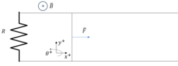
There is a rod of mass ##m## that closes a circuit. The rod can move as shown in the image.
The circuit contains a constant resistance ##R##.
The resistance of the conductor and the rod is negligible.
There is a magnetic field ##B## present that can be considered constant, uniform, and perpendicular to the circuit.
A constant force is applied to the rod.

Using Faraday's law I can find what is the energy consumption on ##R## because of the voltage generated at a given velocity. However, I cannot link that to Newton's laws so I cannot really know how the velocity of the rod changes.
Here is my attempt so far.
$$V=-\frac{d\Phi}{dt}=-\frac{d}{dt}\int \bar{B}d\bar{S}$$
The normal vector to the changing surface is parallel to the magnetic field so the dot product is simplified. This is:
$$\bar{B}d\bar{S}=BdS$$
The change in the surface ##dS## can be described as:
$$dS=ldx$$
From the definition of velocity, ##dx## can be expressed as:
$$\frac{dx}{dt}=v \rightarrow dx=vdt \rightarrow dS=lvdt$$
Going back to the expression of voltage due to the change in magnetic flux on an area, the equation cancels the integral and the derivative over time:
$$V=-\frac{d\Phi}{dt}=-\frac{d}{dt}\int BdS=-\frac{d}{dt}\int Blvdt=-Blv$$
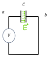
If that voltage is connected to ##R## as initially described, then there will be a current induced in the circuit and power dissipation in the resistance.
$$P=\frac{V^2}{R} = \frac{(-Blv)^2}{R}$$
Given enough time, the problem will be almost stationary. I could use energy conservation to estimate the magnetic "friction" force on the rod.
$$P=\frac{V^2}{R}=Fv \rightarrow F = \frac{B^2l^2v}{R}$$
What is the actual expression of the "magnetic friction"? What I obtained is assuming a few things to get there.
What is the coupled system of equations that links the generation of power due to induction, the circuit, and Newton's laws?
Thanks in advance.
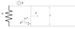
There is a rod of mass ##m## that closes a circuit. The rod can move as shown in the image.
The circuit contains a constant resistance ##R##.
The resistance of the conductor and the rod is negligible.
There is a magnetic field ##B## present that can be considered constant, uniform, and perpendicular to the circuit.
A constant force is applied to the rod.
- Describe the movement of the rod.
- Describe the energy consumption over time.
Using Faraday's law I can find what is the energy consumption on ##R## because of the voltage generated at a given velocity. However, I cannot link that to Newton's laws so I cannot really know how the velocity of the rod changes.
Here is my attempt so far.
$$V=-\frac{d\Phi}{dt}=-\frac{d}{dt}\int \bar{B}d\bar{S}$$
The normal vector to the changing surface is parallel to the magnetic field so the dot product is simplified. This is:
$$\bar{B}d\bar{S}=BdS$$
The change in the surface ##dS## can be described as:
$$dS=ldx$$
From the definition of velocity, ##dx## can be expressed as:
$$\frac{dx}{dt}=v \rightarrow dx=vdt \rightarrow dS=lvdt$$
Going back to the expression of voltage due to the change in magnetic flux on an area, the equation cancels the integral and the derivative over time:
$$V=-\frac{d\Phi}{dt}=-\frac{d}{dt}\int BdS=-\frac{d}{dt}\int Blvdt=-Blv$$
If that voltage is connected to ##R## as initially described, then there will be a current induced in the circuit and power dissipation in the resistance.
$$P=\frac{V^2}{R} = \frac{(-Blv)^2}{R}$$
Given enough time, the problem will be almost stationary. I could use energy conservation to estimate the magnetic "friction" force on the rod.
$$P=\frac{V^2}{R}=Fv \rightarrow F = \frac{B^2l^2v}{R}$$
What is the actual expression of the "magnetic friction"? What I obtained is assuming a few things to get there.
What is the coupled system of equations that links the generation of power due to induction, the circuit, and Newton's laws?
Thanks in advance.