- #1
argyrg
- 3
- 1
- TL;DR Summary
- A length of spring wire, fixed along part of its length and free at the other end. For a given diameter of wire, fixed length and free length how can the torque or lifting power be calculated
I am designing a small box with a lid. The box and its lid measure 100mm x 70mm x 25mm tall..
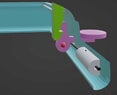
The lid is spring loaded by a suitably designed torsion spring. When the lid is closed it is latched in place horizontally. The latch mechanism consists of a fixed item in the lid and a moveable latch in the base. When the lid closes, its lever pushes the base lever out of the way until the base lever snaps in to place. The latching faces overlap by 1.5mm.
I have a horizontal lever which is 15mm long and 2mm square. The lever operates the base latch. When the lever is pressed it releases the latch and allows the lid to raise under the tension of the torsion spring.
At one end of the horizontal lever, inside the box, there is a hinge / pivot point. At 90 degrees vertical to the horizontal lever is the latch. The lever passes through an aperture in the base of the box which constrains its moveable range from horizontal to -18 degrees. This translates to a movement of more than 1.5mm at the latch interface, therefore sufficient to release the latch
The aperture through which the klever passes in the base of the box is 5mm away from the centre of the hinge. The aperture is 3.3mm tall which means that the 2mm tall lever can be depressed by 1.3mm.
When the lever is depressed (by pressing with a finger or thumb) the spring will act to oppose the movement. When the lever is released the spring will force the lever back to horizontal.
I need to specify a simple spring which will provide sufficient force and a reasonable amount of feedback to the user as the lever moves over this 1.3mm range. I want to avoid creating a spring which is too strong such that it becomes uncomfortable to operate or one that is too weak to return and hold the latch in place.
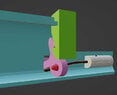
My expectation is that a short length of music wire or stainless wire can be set into a horizontal well in the base of the box on its inside face. The diameter of the well will be slightly larger than that of the music wire spring. The position of the well will allow a length of spring wire to be inserted in to it and for the free end to extend beyond the well and then sit just above the underside of the lever. In this way one end of the wire will be fixed and the free end can be pushed down to put the lever under the desired tension. When the lever is fully depressed it will deflect the spring by a further 1.3mm.
I would like to know how to specify the force that the free end of the wire will create. I think there are three variables.
1. The diameter of the wire to be used
2. The length of the leg in the well
3. The distance between the exit of the well and the far side of the horizontal latch lever (or just beyond it)
Thanks in anticipation
Russell
The lid is spring loaded by a suitably designed torsion spring. When the lid is closed it is latched in place horizontally. The latch mechanism consists of a fixed item in the lid and a moveable latch in the base. When the lid closes, its lever pushes the base lever out of the way until the base lever snaps in to place. The latching faces overlap by 1.5mm.
I have a horizontal lever which is 15mm long and 2mm square. The lever operates the base latch. When the lever is pressed it releases the latch and allows the lid to raise under the tension of the torsion spring.
At one end of the horizontal lever, inside the box, there is a hinge / pivot point. At 90 degrees vertical to the horizontal lever is the latch. The lever passes through an aperture in the base of the box which constrains its moveable range from horizontal to -18 degrees. This translates to a movement of more than 1.5mm at the latch interface, therefore sufficient to release the latch
The aperture through which the klever passes in the base of the box is 5mm away from the centre of the hinge. The aperture is 3.3mm tall which means that the 2mm tall lever can be depressed by 1.3mm.
When the lever is depressed (by pressing with a finger or thumb) the spring will act to oppose the movement. When the lever is released the spring will force the lever back to horizontal.
I need to specify a simple spring which will provide sufficient force and a reasonable amount of feedback to the user as the lever moves over this 1.3mm range. I want to avoid creating a spring which is too strong such that it becomes uncomfortable to operate or one that is too weak to return and hold the latch in place.
My expectation is that a short length of music wire or stainless wire can be set into a horizontal well in the base of the box on its inside face. The diameter of the well will be slightly larger than that of the music wire spring. The position of the well will allow a length of spring wire to be inserted in to it and for the free end to extend beyond the well and then sit just above the underside of the lever. In this way one end of the wire will be fixed and the free end can be pushed down to put the lever under the desired tension. When the lever is fully depressed it will deflect the spring by a further 1.3mm.
I would like to know how to specify the force that the free end of the wire will create. I think there are three variables.
1. The diameter of the wire to be used
2. The length of the leg in the well
3. The distance between the exit of the well and the far side of the horizontal latch lever (or just beyond it)
Thanks in anticipation
Russell