- #36
- 5,614
- 2,935
See https://www.physicsforums.com/threads/a-magnetostatics-problem-of-interest-2.971045/ for additional details. (The "link" was posted previously in post 20).
so let me recap right here to check if I am understand this correctly.Charles Link said:They are computing ## B=\mu_o H ##, where ## H ## is computed just like ## E ##, but for magnetic charges, ## \mu_o ## replaces ## \epsilon_o ##.
## R ## is the radial location on the endface of the cylinder over which ## dA=R \, dR \, d \Phi ## is integrated.
The endfaces have magnetic surface charge density ## \sigma_m=\pm M ##.
## \rho ## is the radial distance in cylindrical coordinates of the point of observation where the field is computed.
One additional item: I like to use ## B=\mu_o H+M ##. They use ## B=\mu_o H+\mu_o M ##, so that their ## \mu_o M ## is my ## M ##.
After computing ## H ## at some observation point outside the material, you then compute ## B=\mu_o H+M ##, but this ## M ## is zero, (outside the material), so ## B=\mu_o H ##.
I think this thread is kind of going in circles and it is not very clear what the problem you want to solve actually is totally. That makes it hard to help you. I understand you want the flux through a loop of wire of an N42 magnet but is it at one point in time of a moving magnet or is it fixed?Einstein44 said:so let me recap right here to check if I am understand this correctly.
From my understanding of cylindrical coordinates, the point z in the equation is simply going to be the height of the cylinder?
For ## \rho ##, usually represents the radio of the cylinder? But in this case you said it is the point where the field is computed. Does this mean ## \rho ## is the distance form the center of the magnet to the point on the coil, as this is where it interacts with the magnetic field of the magnet?
Now what you said about ## R ## I must admit I wasn't able to understand, so I would appreciate if you could formulate this very simply and how I can find this out?
So I am going to start from the beginning now:bob012345 said:I think this thread is kind of going in circles and it is not very clear what the problem you want to solve actually is totally. That makes it hard to help you. I understand you want the flux through a loop of wire of an N42 magnet but is it at one point in time of a moving magnet or is it fixed?
Please, let's back up and refresh what we know. Please clearly state exactly what you are trying to do, maybe even draw the problem and tell us what you know and what exactly you are trying to find out. If it is a homework problem please show us the actual problem.
To answer the immediate questions above, ##z## and ##\rho## are coordinates in a cylindrical system. You should review cylindrical coordinate systems to get the right orientation to the symbols.
https://en.wikipedia.org/wiki/Cylindrical_coordinate_system
This is what I mean though, if ## \rho ## is measured perpendicular to the z axis from the center at the origin, isn't that simply the radius (it goes from the center of the magnet to one end of the circle on top of the magnet)? That can easily be measured? I've drawn this out and this is what I am seeing.Charles Link said:They are summing (integrating) all the contributions to ## B ## (or ## H ##) at a point ## (\rho,z) ## where with cylindrical symmetry, it is independent of ## \phi ##). The radial distance ## \rho ## is measured perpendicular to the z axis. The magnet has center at the origin, with endfaces at ## z=\pm L/2 ##.
The magnet has radius ## a ##, and ## R ## is the radial variable on the endface.
The ##B_z=\mu_o H_z ## is readily computed using the pole model=they used a different approach using the gradient of the magnetic potential, but here I do prefer just computing ## H ## how the electric field ## E ## is computed. You should be able to follow how they did the integral over ## R \, dR \, d \Phi ## in polar coordinates. To get the z-component, there is a simple factor tacked onto the inverse square.
Yes, I understand what you are saying about H and B being different at different points along the magnet. But what exactly does that mean in terms of the variables. I am having trouble understanding how exactly I can measure these components/ what I need to do... I get for example what you are saying about ## \rho ## being measured from the center and perpendicular to the z-axis... But so how is that different from a radius... Do I have to measure this further to some point where the field lines are or what?? I was just looking for a simple answer but I must admit I am quite confused with some of the stuff right now.Charles Link said:The magnetic charge is spread out over the surface of the endface. Let's work it in (x,y,z) coordinates. The z component of the magnetic field ## B_z ## is computed at (x,y,z). Each element ## dx'dy' ## on the endface surface contributes a different amount to ## H ## or ## B ## because of the distance factor, and the direction that the ## H ## points is different as well. (Presumably you are somewhat familiar with the analogous problem with electric charges to compute the electric field ## E_z ##).
Note: ## dx'dy'=R \, dR \, d \Phi ##.
so are you referring to the distance z as the distance from the magnet to the coil?Charles Link said:You just need to compute the flux, (using the z component of ## B ##), through a loop at distance ## z ##:
Flux ## \phi=2 \pi \int\limits_{0}^{b} B_z(\rho) \rho d \rho ##, where ## b ## is the radius of your coil.
First you of course need to compute ## B_z(\rho) ## for each ## \rho ##, (I would suggest about one hundred increments or more), because you don't have a simple expression for ## B_z(\rho)##. That computation also involves a numerical integration, (over ## R \, dR \, d \Phi ##). (## B_z(\rho) ## could be approximated if you considered your magnet to consist of two point poles that are on-axis, and you could then avoid the surface integral, but it really shouldn't be too difficult to numerically compute this double integral over the surfaces of the endfaces).
Ok, thanks. This makes the problem not simpler but at least straightforward.Einstein44 said:So I am going to start from the beginning now:
My aim is to find the induced emf as a cylindrical N42 magnet falls through a coil of N loops.
To calculate this I use Faradays Law.
Now for that, I need to find the magnetic flux in the first place using the equation:
$$\phi =\oint BdAcos\theta$$
This is why I am now trying to find B for the magnet, in order to work out this problem.
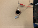
I am attaching a picture below that might perhaps help with visualisation.
So yes, indeed involves a moving magnet.
Yes, this is a picture of my own setup, and yes I am aiming to test results using this setup and have already collected data.bob012345 said:Ok, thanks. This makes the problem not simpler but at least straightforward.
Is that just some photo you found or is it your own setup? I ask because if it is your setup perhaps you already have data to compare to your calculation when that is done.
My recommendation is to forget the loop and any motion for the moment and just calculate the magnetic field from this combined magnet in 3D space for all space in cylindrical coordinates. First pick a convenient location for the origin. There should be enough to informatin above to do that.
After that you will introduce the loops into the picture and calculate the flux at any point along the axis.
Then, since the induced ##emf = - \frac{d\phi}{dt}##, you can move the loop along the axis. The motion of the loop if it is falling is controlled of course by gravity or you can study it for different assumptions, like a fixed velocity for comparison.
z for these formulas is the distance from the center (midway point) of the magnet.Einstein44 said:so are you referring to the distance z as the distance from the magnet to the coil?
And for the second part, what type of increments? Like in what direction? Horizontal? I am still as confused about what exactly you mean
You are getting help on multiple levels at once here. I hope it's not too confusing!Einstein44 said:Yes, this is a picture of my own setup, and yes I am aiming to test results using this setup and have already collected data.
Now as you know I am just trying to find the magnetic field. The origin of what exactly are you taking about? I assume you understand the posts above better than me, so perhaps you could give me a more simple explanation on what the components ## \rho ## , ## z ## and ## R ## represent? I have been trying to figure this out using the posts from @Charles Link , which are really great but somewhat complex to understand for me...
My EM background is not that advanced to be honest, I mean I've covered Biot Savart, Lenzs/ Faradays Law (more familiar with EM induction) than with this kind of stuff to be honest, but I am always willing to learn.bob012345 said:You are getting help on multiple levels at once here. I hope it's not too confusing!
The calculation of the magnetic field everywhere in 3D space is needed in order to know what it is in the loop as the magnet moves through the loop. It is a very difficult calculation. What is your EM background level?
The components ## \rho ## , ## z ## and ##\theta## are the variables of the cylindrical or polar coordinate system. I believe ##R## was used above just to represent integration over the radius of the magnet.
The problem will be ill defined until you establish a fixed coordinate system to work in. That means placing the magnet in that coordinate system say, with the exact center of the magnet at the origin.
Ok, thanks. That is useful.Einstein44 said:My EM background is not that advances to be honest, I mean I've covered Biot Savart, Lenzs/ Faradays Law (more familiar with EM induction) than with this kind of stuff to be honest, but I am always willing to learn.
So from post #49 I understand that z is the distance from the center point of the magnet (now the question is TO where), so I assume what is means is the distance to the coil from that point? Please tell me if I am correct, because looking at the Cylindrical coordinated, the z component is vertical and not horizontal (## \rho ##).
Does this assume most of the field outside the magnet is small compared to the magnet itself with respect to the size of the loop? Is this essentially assuming the loop is just barely bigger than the magnet?Charles Link said:and a follow-on: It might be asking a lot for you to follow some of the advanced physics and complicated integrals above, when there is a shortcut that should get you reasonably accurate results:
(Note: I see I did make one error above: ## B_z(\rho) ## should be ## B_z(\rho, z) ##).
Here we are going to have an approximation for ## B_z ## that is independent of ## \rho ##, and we will call it ## B_z(z) ##:
## B_z(z)=\mu_o M (\frac{ a^2}{4})(\frac{1}{(z-L/2)^2}-\frac{1}{(z+L/2)^2}) ##
and flux ## \phi=B_z(z) \pi b^2 ##, where ## b ## is the radius of the coil. (If you have ## N ## loops in the coil, you need to multiply by ## N ##).
Here ## \mu_o M=1.28 ## T.
The above formulas involve approximations, but they should give you a very good approximate result.
Scratch that=I see I goofed. Sorry.bob012345 said:Does this assume most of the field outside the magnet is small compared to the magnet itself with respect to the size of the loop? Is this essentially assuming the loop is just barely bigger than the magnet?
Who's formula's and what does that part mean? Crosses over means something different than cuts across or the same?Charles Link said:Scratch that=I see I goofed. Sorry.
Edit: One other problem I see now is we are computing the field outside the magnet, using their formulas, but we also need to treat the case where the material of the magnet crosses over the plane of the coil=we need to include the extra term. It's not real difficult to include this part, but it complicates the problem.
My formula for post 54 would work fairly well when the magnet is far from the coil. We've been using the OP's "link" of post 25 to compute the field, but I don't think it works for ## -L/2<z<+L/2 ##. In fact, I think that region needs to be treated with additional details. I think the additional calculations will be fairly routine in any case. (Edit note: See post 60 for the necessary corrections to the formula of post 25).bob012345 said:Who's formula's and what does that part mean? Crosses over means something different than cuts across or the same?
Is the OP doing them?Charles Link said:The ## B_z(\rho, z) ## field outside the magnet (## \rho>a ##) should be ok. If I'm not mistaken, (I will need to double-check this), for ## \rho<a ## with ## -L/2<z<+L/2 ##, all that may be necessary is to add a term ## +\mu_o M ## to ## B_z(\rho, z) ##.
Meanwhile, to answer post 59, the integrals are being done numerically.
See posts 45 and 46 and 49. That's the direction that I'm hoping it goes. It appears even numerical integration may be new to the OP.bob012345 said:Is the OP doing them?
I think it would be instructive to use your simplified model first so the OP can get the mechanics of the problem down by direct integration. Once the essential features of the physics are captured, the numerical integration can be attempted but it is up to the OP.Charles Link said:See posts 45 and 46 and 49. That's the direction that I'm hoping it goes. It appears even numerical integration may be new to the OP.
Looking it over some more, I think my result of post 60 is correct, and that makes things easier than I originally anticipated. The physics including the pole model could be explained in more detail, but the numerical integrals should be very manageable, and I look forward to seeing how the OP @Einstein44 does with them. :) Posts 25, 45, and 60 contain most of what the OP needs. (Note: I've added some detail to posts 45 and 60 to make them easier to follow).bob012345 said:I think it would be instructive to use your simplified model first so the OP can get the mechanics of the problem down by direct integration. Once the essential features of the physics are captured, the numerical integration can be attempted but it is up to the OP.
For the part where you say that the flux would have to be multiplied by N loops, don't you simply have to multiply this using Faradays Law for N loops at then end? Or are you saying you also have to multiply the flux before handCharles Link said:and a follow-on: It might be asking a lot for you to follow some of the advanced physics and complicated integrals above, when there is a shortcut that should get you reasonably accurate results:
(Note: I see I did make one error above: ## B_z(\rho) ## should be ## B_z(\rho, z) ##).
Here we are going to have an approximation for ## B_z ## that is independent of ## \rho ##, and we will call it ## B_z(z) ##:
## B_z(z)=\mu_o M (\frac{ a^2}{4})(\frac{1}{(z-L/2)^2}-\frac{1}{(z+L/2)^2}) ##
and flux ## \phi=B_z(z) \pi b^2 ##, where ## b ## is the radius of the coil. (If you have ## N ## loops in the coil, you need to multiply by ## N ##).
Here ## \mu_o M=1.28 ## T.
The above formulas involve approximations, Edit: and I see I goofed. They don't work as good as I thought they might. They only work well if ## z-L/2>> a ## and it helps to have ## z-L/2>> b ## as well.
Faraday’s experiments showed that the EMF induced by a change in magnetic flux depends on only a few factors. First, EMF is directly proportional to the change in flux Δ. Second, EMF is greatest when the change in time Δt is smallest—that is, EMF is inversely proportional to Δt. Finally, if a coil has N turns, an EMF will be produced that is N times greater than for a single coil, so that EMF is directly proportional to N. The equation for the EMF induced by a change in magnetic flux is;Einstein44 said:For the part where you say that the flux would have to be multiplied by N loops, don't you simply have to multiply this using Faradays Law for N loops at then end? Or are you saying you also have to multiply the flux before hand
Exactly what I meant, so since the N turns are already mentioned in Faradays Law for N loops, there is no need to multiply the flux by the number of loops am I correct? Just making sure because that's what @Charles Link mentioned.bob012345 said:Faraday’s experiments showed that the EMF induced by a change in magnetic flux depends on only a few factors. First, EMF is directly proportional to the change in flux Δ. Second, EMF is greatest when the change in time Δt is smallest—that is, EMF is inversely proportional to Δt. Finally, if a coil has N turns, an EMF will be produced that is N times greater than for a single coil, so that EMF is directly proportional to N. The equation for the EMF induced by a change in magnetic flux is;
$$EMF=−N\frac{ΔΦ}{Δt}$$ or in the limit;
$$EMF =−N\frac{dΦ}{dt}$$
https://courses.lumenlearning.com/b...ter/magnetic-flux-induction-and-faradays-law/
I tried downloading this, had a few issues so I tried something different (I don't know its validity)...bob012345 said:I found this free Python package that computes magnetic fields for various shapes;
https://www.sciencedirect.com/science/article/pii/S2352711020300170?via=ihub
Where does that first expression even come from?Charles Link said:and a follow-on: It might be asking a lot for you to follow some of the advanced physics and complicated integrals above, when there is a shortcut that should get you reasonably accurate results:
(Note: I see I did make one error above: ## B_z(\rho) ## should be ## B_z(\rho, z) ##).
Here we are going to have an approximation for ## B_z ## that is independent of ## \rho ##, and we will call it ## B_z(z) ##:
## B_z(z)=\mu_o M (\frac{ a^2}{4})(\frac{1}{(z-L/2)^2}-\frac{1}{(z+L/2)^2}) ##
and flux ## \phi=B_z(z) \pi b^2 ##, where ## b ## is the radius of the coil. (If you have ## N ## loops in the coil, you need to multiply by ## N ##).
Here ## \mu_o M=1.28 ## T.
The above formulas involve approximations, Edit: and I see I goofed. They don't work as good as I thought they might. They only work well if ## z-L/2>> a ## and it helps to have ## z-L/2>> b ## as well.