- #1
BrentK
- 21
- 0
I seem to have come across a new problem
I am trying to programm a sloping pipe system to match an array of vector points.
I thought I had it all sorted out until I tested with a very high slope angle. With a normal slope of around 2% everything looks fine. If I increase the slope to 30% there seems to be an error in the angle of the corners related to the slope of the pipe. As I increase the slope of the pipe, the error increases.
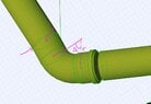
Below is a detail picture of the system at slope 30%.
I calculate the angle difference between the leading and preceding Vector to the corner. This calculation must be correct because the pipes are placed at this angle and are parallel to the vector lines.
I use this same calculated angle to create the pipe corners. Angle "A" in the first picture.
Radius of the corner is "r" and known
Point "1" in the picture shows the end point of the corner, which should line up with the preceding vector... if you look closely you see an error here, meaning the angle needs to be corrected somehow relating to the slope of the pipe system.
Point "2" shows the overlapping points of the corner to the preceding pipe, showing the error in the angle of the corner.
I'm sorry I'm at a loss to be able to explain this in mathmatical terms with some kind of angle diagram, as I am not sure exactly where the problem lies.
If anyone can figure out how i may go about correcting the angle of the corners i would be very grateful!
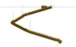
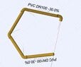
See also 2 pictures showing the pipe system in side view (at 30% slope) and top view.
View attachment 8697
View attachment 8695
View attachment 8696
I am trying to programm a sloping pipe system to match an array of vector points.
I thought I had it all sorted out until I tested with a very high slope angle. With a normal slope of around 2% everything looks fine. If I increase the slope to 30% there seems to be an error in the angle of the corners related to the slope of the pipe. As I increase the slope of the pipe, the error increases.
Below is a detail picture of the system at slope 30%.
I calculate the angle difference between the leading and preceding Vector to the corner. This calculation must be correct because the pipes are placed at this angle and are parallel to the vector lines.
I use this same calculated angle to create the pipe corners. Angle "A" in the first picture.
Radius of the corner is "r" and known
Point "1" in the picture shows the end point of the corner, which should line up with the preceding vector... if you look closely you see an error here, meaning the angle needs to be corrected somehow relating to the slope of the pipe system.
Point "2" shows the overlapping points of the corner to the preceding pipe, showing the error in the angle of the corner.
I'm sorry I'm at a loss to be able to explain this in mathmatical terms with some kind of angle diagram, as I am not sure exactly where the problem lies.
If anyone can figure out how i may go about correcting the angle of the corners i would be very grateful!
See also 2 pictures showing the pipe system in side view (at 30% slope) and top view.
View attachment 8697
View attachment 8695
View attachment 8696