- #1,646
Zippi
- 3
- 2
Thanks Mike! I'll PM you as to rules and the location of where we run. We showed up last year with the car, and the old timers recognized us right away. Got warned about rule interpretation pretty quick LOL
We prefer that discussions be held in the open forums instead of in PM conversations. But I guess if you're going to be asking for advice for how to get around the track rules, a PM conversation might be the best choice...Zippi said:Thanks Mike! I'll PM you as to rules and the location of where we run. We showed up last year with the car, and the old timers recognized us right away. Got warned about rule interpretation pretty quick LOL
I see what you did there...Ranger Mike said:We are not re-inventing the wheel here.

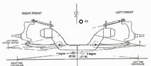
Hi RMRanger Mike said:Body roll and RC location
Back on Page 14, post # 479 I used an illustration not to scale but relative to the point. The front Roll Center location matters greatly in the performance of the race car. Below illustration has the RC way up there at about 13” above the track. The Center of Gravity is about 16” above the track. Not to realistic. The pic below is a lot more real world with the Roll center up about 3 inch and 3 inch to the right of center. The CG is offset to the left 1 inch as most rules permit it.
Down force quick tutorial - Take a tire ( mounted on the wheel of course) and stand it up on its wide tread. Now facing the wheel Grip both sides like you are going to put it on the wheel lugs. Slide it on the garage floor. Slides pretty easy, right? Now have Lumpy the fat neighbor kid, sit on the tire and try this again. Sliding a 40 pound tire/wheel was easy but sliding a 165 pound tire/wheel/ fat kid set up is way more difficult. This is what happens when you add DOWN FORCE. More grip.
Increasing the amount of vertical downforce on the right front tire increases the available traction, but in a non-linear way. When you increase loading on a tire, it will gain traction, but not in constant multiples. Adding 706 lbs down force adds traction but if we double it the results will not double the traction. The amount of traction will be something less than 2 times.
Big Bar and Soft Spring setups - This setup limits body roll in an attempt to place more load on the left-side tires, leading to more equally loaded sets of tires to produce more traction. One major factor is to limit the air under the car and kill off lift. Initially when this set up developed ride heights were about 4 inch track to chassis now it is 3 inch. Everyone is going lower. This and a more aero body adds downforce on the car body to provide tire loading. You still need to take advantage of RC location to properly load the right front tire.
Per attached pic note -
Left RC has a 4° angle to the right front tire contact patch. The Right side RC has a 6° angle. This is the jacking effect that can lift the left side tire if it is great enough. Remember the sprint cars carrying the left front tire off the ground thru the turns. This happens when the roll center is placed too far to the right of centerline.
Note the longer moment arm or lever between the CG and the Rt RC.
Now let us look at what happens during cornering. Momentum will continue to travel in a straight line until another force changes the direction. In this case the tires will do this through the suspension linkages.
Now let us look at the MASS that will have Momentum and must be dealt with before the car starts pushing like a freight train. Typical Late Model car min wight limit is 3000 lbs.
Of this, Unsprung weight of quick change, coil overs (50% unsprung weight, sway bar (ARB), upper control arms) amount to 400 lbs. We need to handle 2600 lbs. mass.
On a typical race car the front to rear weight is 52-48%. Caution- the calculations here are not going to be accurate but are close enough to demonstrate the need for proper location of the front roll center. In this example 52% of 2600 lbs is 1352 lbs.
This Mass will continue forward or diagonal once the tires cause opposing force on the MASS. One force vector is from the right front tire to the Roll Center.
If we know the Angle Sine of the left RC has a 4° angle has SIN of 0.07. and we multiply this by the 1352 Mass we have 95 lbs. acting on the tire contact patch thru this vector and the remaining 1257 lbs. moving laterally to the outside of the track. But wait a minute. What also is happening during the cornering process.
The typical late model car has 34” between the front spring upper mounting points. Our left roll center is offset 3 inches to the left which means 42% of the body roll will act on this RC. We have 42% of the Mass moving thru the RC rotating and planting the right front tire with 528 lbs. downforce. The remaining 1402 lbs. is moving laterally and pushing directly on the tires.
Now let us look at the Angle Sine of the right RC, 6° angle has SIN of 0.10 and we multiply this by the Mass we have 135 lbs. acting on the tire contact patch thru this vector and the remaining 1217 lbs. moving laterally to the outside of the track. But wait a minute. What also is happening during the cornering process.
The typical late model car has 34” between the front spring upper mounting points. Our right roll center is offset 3 inches to the right. Now we have 58% of the body roll rotating thru this RC. We have 58% of the Mass moving thru the RC rotating and planting the right front tire with 706 lbs. downforce. The remaining 511 lbs. is moving laterally and pushing directly on the tires.
Feature ................................ Left RC......................Right RC
Downforce on rt ft tire......528 lbs...................706 lbs or 25% more downforce
Force lateral thru tire...........1402 lbs..............511 lbs
Jacking force rt ft tire............95 lbs.................135 lbs
I would prefer 25% more down force on the right front tire and handle the momentum with this set up as opposed to the left side roll center method.
One is that the BBSS car has more inside load and the only things that can change load transfer with a given velocity and turn radius is the track width and COG height. There may be a slight change from COG not rising but that is probably controlled more with jacking forces.Totally Wrong. *I have intentionally not factored in acceleration ( G force is a measure of acceleration). This would complicate the issue. Turn radius, COG height, RC height have no impact on the force of the car going into the turn. When the car gets to the max apex of the turn the only consideration is how to deal with the force of the momentum. Granted, the more Aero downforce you can apply before the turn the more the sprig package will compress. On ½ mile tracks this is a factor.UFO said:Hi RM
I like this site there is a lot of things you bring to light and explain in a way to make it easy to under stand. There is a couple of things in this post don't sound right to me. One is that the BBSS car has more inside load and the only things that can can change load transfer with a given velocity and turn radius is the track width and COG height. There may be a slight change from COG not rising but that is probably controlled more with jacking forces.
The other thing is your explanation of load transfer on front end verses roll center height. This has the same argument as above, RCH, spring rate, and jacking effect can not change load transfer only how fast it takes place and how its distributed. RCH determines how much of the load transfer is handled by geometric forces and elastic forces. Any jacking forces that happen are subtracted from the elastic forces, or the difference of how much the inside spring got lighter and the outside spring got heavier.
So I don't think it matters where you put the roll center height or lateral position the steady state vertical load on the RF tire, in the turn, will not change. The lateral force on the front will be the static weight of the front end times the lateral G force, on a flat track, a little more complicated for banking. Please let me know if you think I have something wrong.
track width | Center line | Ideal location for the 58%** | Difference |
70 | 35 | 40.6 | 5.6 |
69 | 34.5 | 40.02 | 5.52 |
68 | 34 | 39.44 | 5.44 |
67 | 33.5 | 38.86 | 5.36 |
66 | 33 | 38.28 | 5.28 |
65 | 32.5 | 37.7 | 5.2 |
64 | 32 | 37.12 | 5.12 |
63 | 31.5 | 36.54 | 5.04 |
What is a "traditional roll center"? If the roll center is above ground, there is always a jacking force.Savem c10 said:I’m looking at roll center geometry there two different styles. A traditional or conventional roll center and jacking force which one is more consistent or better on tires and why ?
With a traditional style roll center they are usually located to the right of the center line with jacking force they are located left of the center line. Maybe Ranger Mike could shed some light on this .jack action said:What is a "traditional roll center"? If the roll center is above ground, there is always a jacking force.
Ranger Mike said:see post 1654 above
Well RM I am conflicted right now because I’ve measured out my role centers and currently I’m sitting at 2 5/8 left of the centerline and 3 5/8 above ground and I know that you recommend 2 inches to the right of the centerline and 2 inches above ground, but I’ve heard some conflicting arguments about having the role center too far to the right as the car would last like 10 laps and go away versus the role center being to the left and giving the car longevity. Very unsure if I should move them or leave them where they’re at what would you recommend?Ranger Mike said:see post 1654 above
Ranger Mike said:Actually, I recommend front roll center to be 2" to 2.5" above the ground and 2.5" to 3" to the right of centerline. This is for traditional or BBSS set up.
Are you using chassis center line of tire track width center line?
Can we agree that your 3 5/8 rc ht is a bit high for a paved track late model on 8 inch tires?
Can we agree that those spec tires need more down force to stick?
do you have tire temps for last long race?
You said -
I’ve heard some conflicting arguments about having the role center too far to the right as the car would last like 10 laps and go away versus the role center being to the left and giving the car longevity. Very unsure if I should move them or leave them where they’re at what would you recommend?
RM life lesson- ifin you want to keep getting what you been getting , stay in your lane and do nothing.
You want to WIN, take the chance, you only live ONCE. Winning is NOT for everyone.
I have to admit RM most of the calculations are you putting forward to me are beyond my pay grade let’s say I’m not too familiar with trigonometry, but I’ve watched a few videos on what sin is and the calculations of it but not 100% confident on understanding of it. i’ve mapped out the role centers and tryed posting a picture for u .ill try again . I bought the Steve smith book u recommend laying the front end just it states in the book . I set the roll center at 2 5/8 off the and 2 5/8 right of the center line as I can move theses a with the upper a frame angles if need be . Figured this would be a good starting point.Ranger Mike said:Here are your numbers
On a typical race car the front to rear weight is 52-48%. Caution- the calculations here are not going to be accurate but are close enough to demonstrate the need for proper location of the front roll center. In this example 52% of 2600 lbs is 1352 lbs.
This Mass will continue forward or diagonal once the tires cause opposing force on the MASS. One force vector is from the right front tire to the Roll Center.
If we know the Angle Sine of the left RC has a 115° angle has SIN of 0.190 and we multiply this by the 1352 Mass we have 257 lbs. acting on the tire contact patch thru this vector and the remaining 1095 lbs. moving laterally to the outside of the track. But wait a minute. What also is happening during the cornering process.
The Your late model car has 34” between the front spring upper mounting points. Our left roll center is offset 2 5/8 inches to the left which means 49% of the body roll will act on this RC. We have 49% of the Mass (1095) moving thru the RC rotating and planting the right front tire with 460 lbs. downforce. The remaining 635 lbs. is moving laterally and pushing directly on the tires.
Now let us look at the Angle Sine of the right RC, 5° angle has SIN of 0.087 and we multiply this by the Mass (1352) we have 118 lbs. acting on the tire contact patch thru this vector and the remaining 1234 lbs. moving laterally to the outside of the track. But wait a minute. What also is happening during the cornering process.
The typical late model car has 34” between the front spring upper mounting points. Our right roll center is offset 3 inches to the right. Now we have 52% of the body roll rotating thru this RC. We have 52% of the Mass (1234) moving thru the RC rotating and planting the right front tire with 642 lbs. downforce. The remaining 592 lbs. is moving laterally and pushing directly on the tires.
Feature ................................ Left RC......................Right RC
Downforce on rt ft tire......460 lbs...................642 lbs. or 40% more downforce
Force lateral thru tire...........635 lbs..............592 lbs. side load
Jacking force rt ft tire............257 lbs.................118 lbs.
You are running just about 3 times the jacking force with current set up.
I would bet you are running a stiff right rear spring (300#) to keep the left front from lifting. keep an eye on this! may need change.
The side loads are close but on those hard spec tires you need more down force to out corner the other racers to plant the right front tire and pivot the car in the turn.
Finally, have you ever heard of these hard spec tires going away in ten laps? Adding 182 pound down force and taking away 140 pounds jacking force is going to burn a tire in 10 laps...
Granted, this example is NOT for YOUR car. It is an example of RC location and impact on a spec tire car. So take it worth what it is worth. Opinions are is free. nuff said?
There some additional line here just figure out different a frame lengths and height I have lower frame set a correct heights . The thing I most curious about is how much migration I will get . I’m assuming I don’t want much .Savem c10 said:I have to admit RM most of the calculations are you putting forward to me are beyond my pay grade let’s say I’m not too familiar with trigonometry, but I’ve watched a few videos on what sin is and the calculations of it but not 100% confident on understanding of it. i’ve mapped out the role centers and tryed posting a picture for u .ill try again . I bought the Steve smith book u recommend laying the front end just it states in the book . I set the roll center at 2 5/8 off the and 2 5/8 right of the center line as I can move theses a with the upper a frame angles if need be . Figured this would be a good starting point. View attachment 341203View attachment 341203
That helps RM . I’m taking a short course trig for dummies . Another question I have .,How much travel should we be getting? And if we travel the car to far how badly does interrup the roll center and its ability to plant the Right front tire.How far off the ground should the cross member be when at full travel ?Ranger Mike said:Regarding Roll Center acting on right front tire contact patch.
Look at the diagram. We have a block placed on a slope. The forces acting on t his block are its Mass and Gravity.
Parallel force can be found using the formula: Fparallel = m * g * sin(θ) where:
Fparallel is the parallel force, - m is the mass of the object, g is the acceleration due to gravity (approximately 9.8 m/s2 on Earth), and θ is the angle of the inclined plane with respect to the horizontal.
For this exercise we can leave out G as gravity will effect both Roll Center setups the same. This leaves the equation Fparallel = m * sin(θ). or W times Sine θ
Note - θ is Theta angle in degrees.
For our race car we have the sprung weight of the car going into the corner and pushing from the Roll Center to the rt ft tire contact patch. If we know the total mass as previously calculated in the above example post # 1674, we have to deal with 1352 lbs. pushing directly on the rt ft tire contact patch at an angle of 11°
Sine of θ from Trig tables -
Sine of 90° = 1
Sine of 45° = 0.70
Sine of 30°= 0.50
Sine of 11°= 0.19
Sine of 5° = 0.08
So you see when you multiply 1352 x 11° angle with Sine of .19 = 257 lbs.
Now compared to 1352 x 5° angle with Sine of 0.08 = 108 lbs.
the smaller the angle, the less force results, everything else being equal.
This is why we always want to apply for at 90° to the object to get maximum applied force!