- #1
Exploring Link Movement in X-Y-Z Axis: How Does This Linkage Rotate and Yaw?

Related to Exploring Link Movement in X-Y-Z Axis: How Does This Linkage Rotate and Yaw?
What is link movement in the X-Y-Z axis?
Link movement in the X-Y-Z axis refers to the motion of a mechanical link in three-dimensional space, where X, Y, and Z represent the directional axes. This movement can include linear displacement as well as rotational movements around any of these axes.
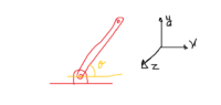
How does a linkage rotate and yaw?
A linkage rotates around an axis when it follows a circular path, which can be around the X, Y, or Z axis. Yaw refers to rotation around the vertical (typically Z) axis, similar to the motion seen in the steering of a car. This rotation and yaw are controlled by the joints and configuration of the linkage which dictate the range and plane of motion.
What are the common applications of these movements in robotics and machinery?
In robotics, these movements are crucial for tasks requiring high precision and flexibility such as in automated assembly lines, robotic arms, and drones. In machinery, they are used in applications like CNC machines and 3D printers where precise, multi-axis control is necessary for the fabrication of complex parts.
What factors affect the efficiency of linkage movement in different axes?
Factors that affect efficiency include the design of the linkage, the type of joints used, material properties, the load carried by the system, and the precision in control mechanisms. Friction, wear and tear, and external environmental conditions also play significant roles in influencing efficiency.
How can one optimize the motion of a linkage in the X-Y-Z axis?
Optimizing the motion of a linkage involves improving its design and control strategies. This can be achieved by using computer simulations to predict movement behaviors and identify optimal configurations. Additionally, selecting appropriate materials and joint types, as well as implementing precise and responsive control systems, are crucial for enhancing performance.
Similar threads
-
Mechanical Engineering
-
Mechanical Engineering
-
Introductory Physics Homework Help
-
Quantum Physics
-
Special and General Relativity
-
General Math
-
Classical Physics
-
General Math
-
Introductory Physics Homework Help