- #1
qwertypo
- 4
- 0
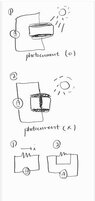
Hi, I'm wondering why shorted circuit geometry like figure 2 did not sense photocurrent?
Even if the the circuit composed like 2, I guess that by the Kirchhoff's Law, voltage should apply to the ampere meter and photocurrent should be sensed. But in real experiment, I found that shorted circuit geometry like 2 cannott sense the photocurrent. What am I missing ? Thanks.
Even if the the circuit composed like 2, I guess that by the Kirchhoff's Law, voltage should apply to the ampere meter and photocurrent should be sensed. But in real experiment, I found that shorted circuit geometry like 2 cannott sense the photocurrent. What am I missing ? Thanks.