- #1
vord_ler
- 12
- 0
- Homework Statement
- Good afternoon, I am having a problem to understand how to set up the current directions when analyzing a circuit using KVL and KCL. I know that it's probably solvable using other more advanced techniques, such as NVM (node-voltage method) or mesh-current method, but it's not yet covered in my classes and in the book, so I want to understand the algorithm on how to find the current directions properly in order to apply the KVL and KCL. I also would like to get some hints on how to apply the KVL and KCL to the given circuit, after defining the current directions. I already tried to solve the problem by setting up the currents going out of the node, but the final answer is usually not correct.
- Relevant Equations
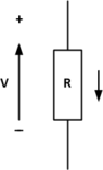
- V = i*R
 ##\qquad##!

 ##\ ##
") ).
).