Crane at 45-degree angle supports load -- Find principal boom stresses

  • #1
SoylentBlue
50
8
Homework Statement
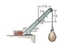
The crane is used to support the 350-lb load.
Determine the principal stresses acting in the boom at
points A and B. The cross section is rectangular and has a
width of 6 in. and a thickness of 3 in.
Relevant Equations
axial stress = P/A; bending stress = Mc/I
transverse shear stress=VQ/IT; torsional stress = Tc/J
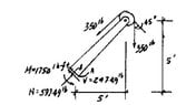
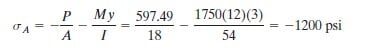
The book's answer key shows a normal stress P/A as a result of adding the 350LB force from the cable to the cos(45 degrees)(350LB). It shows both of these as compressive forces. I can see how the cos(45 degrees)(350LB) is compressive; the force of the 350LB load is bending the boom clockwise, causing compression at point A. But the cable's pull from the 350LB load, intuitively, seems like it should be tension and therefore positive.

Thank you in advance for any help. I am trying to learn this on my own, so I have no professor or other students to talk with; the Internet is my professor.
 

Attachments

  • prob994a.jpg
    prob994a.jpg
    5.3 KB · Views: 4
  • prob994b.jpg
    prob994b.jpg
    6.4 KB · Views: 3
  • prob994c.jpg
    prob994c.jpg
    2.9 KB · Views: 3
Physics news on Phys.org
  • #2
I can’t clearly see in the diagram where points A and B are located in the cross section of the boom.
Could you clarify that, as well as your main question, please?
 
  • #3
The book's answer key shows, for point A, sigma = P/A = 597.49/18 in compression. The 597 is the sum of [cos(45 degrees)(350LB)] plus 350LB. cos(45 degrees)(350LB) is 247LB, which is bending the boom clockwise, therefore putting point A in compression. The additional 350 must come from the cable, which, by the arrow they have drawn, is in compression. I don't see how a cable can be in compression.
I agree that it is difficult, the way they drew this, to determine where points A & B are; I needed a magnifying glass to decipher their schematic.
The side of the boom, which we see in the illustration, is 6 inches; it is 3 inches deep.
If we look straight-on at the cross-section of the boom, where it is 6in tall and 3in wide, point A is on the bottom-right corner of the boom. Point B is on the right side edge, 3in up from the bottom; it is on the neutral axis.
Thank you in advance :^)
 
  • Like
Likes Lnewqban
  • #4
In order to understand the load on the boom, we need to do a free body diagram of it.
The boom "knows" nothing about the cable or the load.
All the forces reach it through the shaft of the pulley and its solid anchorage to the ground.

Crane 1.jpg


Crane 2.jpg


Crane 3.jpg
 
Last edited:
  • #5
Oh, I see. It was just a matter of geometry. Thank you, thank you! :^)
 
  • Like
Likes Lnewqban
  • #6
@SoylentBlue ,
Now that we have identified direction and value of the actual external force that the load imposes onto the crane, shall we continue our discussion regarding internal forces deep into the boom (at cross-section A-B)?

Crane 4.jpg
 
  • #7
OK, here's a summary of the forces at points A & B:

I = 1/12(base)(height)3 = 1/12(3)(6)3 = 54

Q = y-bar*area = 1.5 * 9 = 13.5 where area is 3 high and 3 deep

For point A:

Normal force = P/A = -597/18 this is negative since it is in compression

Bending moment= Mc/I = [(7.07ft)(12inches/1ft)(3in)]/54 = -1164 psi

Moment is also negative since point A is in compression

Sigma total = -1200 psi


Tau = Tc/J = 0 there is no torsion

Tau= VQ/IT= 0 because q = 0 ; A is on outer edge, and there is no material above it


For point B:

Normal force = P/A = -597/18 this is negative since it is in compression

Bending moment= Mc/I = 0 since B is on the neutral axis

Sigma total = -33.19 psi


Tau = TC/J = 0 there is no torsion

Tau= VQ/IT= (247*13.5)/(54*3) = 20.62 this is positive since our shearing force goes up


I am still a little unsure about determining the signs of torsion and transverse shear. Do we always apply the right-hand rule? For instance, in problem 9-91 (where we have a pipe wrench on a pipe; screenshot attached), if we apply the right-hand rule, the wrench spins the pipe into the paper about the x axis, and the thumb points up; wouldn't this be positive torsion?

Thank you again. I wish I was young enough to go back to school and finish the engineering degree that I started (but never finished) back when Jimmy Carter was still President.
 

Attachments

  • Prob991.jpg
    Prob991.jpg
    36.9 KB · Views: 1
  • Like
Likes Lnewqban
  • #8
Addendum to last post: I did a quick review of statics, and I see that M, N and V are internal forces. The torsion and shear due to the pipe wrench are external forces. So of course the internal and external reactions would have to oppose each other, just as they show in the answer key's illustration. I am embarrassed to admit that I missed that.
 
  • Informative
  • Like
Likes berkeman and Lnewqban

Similar threads

Replies
2
Views
704
Replies
5
Views
4K
  • Mechanical Engineering
Replies
5
Views
127
  • Engineering and Comp Sci Homework Help
Replies
17
Views
4K
  • Engineering and Comp Sci Homework Help
Replies
4
Views
5K
  • Engineering and Comp Sci Homework Help
Replies
16
Views
7K
  • Engineering and Comp Sci Homework Help
Replies
1
Views
3K
  • Mechanical Engineering
Replies
1
Views
5K
  • Introductory Physics Homework Help
Replies
4
Views
2K
Replies
8
Views
9K
Back
Top