Change the application pole of the moment of a force

In summary, the conversation involves an aerospace engineer working on a thesis and seeking help in solving a problem related to calculating the moment acting on an aeordynamic body. The engineer is unsure about the use of forces from CFD analysis and is struggling with applying a mathematical law to the problem. The expert suggests simplifying the problem and comparing simulation results to published data to properly interpret the results. The expert also advises starting with simulating 2D flow around a cylinder and then an ellipse before tackling the more complex problem.
  • #1
Marco9518
18
1
Good morning everyone!

I am an aerospace engineering working on my thesis and i am trying to solve a little problem.

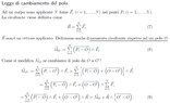
In the picture you can see an "aeordynamic" body. The CFD analysis gives me the forces and the moments acting on this body. How can i calculate the momentum acting on the body with respect to O'? In particular, how do i find "R"? I want to point out that the moments that the CFD gives me are just values!

Thank you very much to everyone!
 

Attachments

  • photo_2021-08-14_14-07-19.jpg
    photo_2021-08-14_14-07-19.jpg
    32.4 KB · Views: 130
Last edited:
Engineering news on Phys.org
  • #2
Is it possible that you are confusing momentum and moment?
 
  • #3
Lnewqban said:
Is it possible that you are confusing momentum and moment?
Oh yes for sure! I am just not very good with the language but I was talking about moment!
 
  • #4
If I understand the diagram correctly, there are no forces acting on the body, only moment Mc about point O.
 
  • #5
Lnewqban said:
If I understand the diagram correctly, there are no forces acting on the body, only moment Mc about point O.
I did not draw forces but only because i wanted to focus on the moments.
What i have is basically a chart that says for, every angle of attack, the value of the forces and the moments acting on the 3 axis, in the Oxyz frame of reference.
 
  • #6
I see.
Next question: Could you describe the meaning of the equation shown in the diagram?
 
  • #7
Lnewqban said:
I see.
Next question: Could you describe the meaning of the equation shown in the diagram?
It is the law used to change the pole of the moment. The problem i think is just R which is defined as the summation for "i" that goes from 0 to N of F(i). But i am not very sure if i can use the forces coming from the CFD.
 
  • #8
Sorry, Marco, I can't understand this problem.
 
  • #9
I have no idea what the "pole of a moment" is, but do have some experience at interpreting computer software results. There are some basic principles that apply to all computer simulation programs, whether CFD, CAD, or motion analysis. You need to learn how to interpret the software results.

Start by simplifying your problem, which seems to be related to 2D flow around an ellipse. If you are, in fact, studying 2D flow around an ellipse, start by simulating 2D flow around a cylinder. Then you have simulation results that can be directly compared to published data. The process of comparing to published data is where you learn to interpret the results, and also learn if you properly simulated the problem.

The next step is 2D flow around an ellipse, where the flow is aligned with the ellipse major axis. These results can also be compared to published data.

Your mention of moments implies that your flow is not aligned with either the ellipse major or minor axis. If so, there is published data for the case of finite major axis, and minor axis of length zero. It's called a flat plate. Run the simulation for a range of angles, and compare to published results.

You should now be able to run the case of an ellipse with 2D flow not aligned with either the major or minor axis.

CFD is completely different from linear static FEA, and the learning curve is much longer. A person learning CFD can easily take 2 or 3 months of full time work to properly perform the above verification tests.
 
  • #10
Has R been defined somewhere?
 
  • #11
hutchphd said:
Has R been defined somewhere?
R is defined as the summation for "i" that goes from 0 to N of F(i).
But i am not very sure if i can use the forces coming from the CFD.
The law that i wrote in the picture is one of the basis in mathematical physics but it seems like nobody is able to apply it, including me obviously.
 
  • #12
jrmichler said:
I have no idea what the "pole of a moment" is, but do have some experience at interpreting computer software results. There are some basic principles that apply to all computer simulation programs, whether CFD, CAD, or motion analysis. You need to learn how to interpret the software results.

Start by simplifying your problem, which seems to be related to 2D flow around an ellipse. If you are, in fact, studying 2D flow around an ellipse, start by simulating 2D flow around a cylinder. Then you have simulation results that can be directly compared to published data. The process of comparing to published data is where you learn to interpret the results, and also learn if you properly simulated the problem.

The next step is 2D flow around an ellipse, where the flow is aligned with the ellipse major axis. These results can also be compared to published data.

Your mention of moments implies that your flow is not aligned with either the ellipse major or minor axis. If so, there is published data for the case of finite major axis, and minor axis of length zero. It's called a flat plate. Run the simulation for a range of angles, and compare to published results.

You should now be able to run the case of an ellipse with 2D flow not aligned with either the major or minor axis.

CFD is completely different from linear static FEA, and the learning curve is much longer. A person learning CFD can easily take 2 or 3 months of full time work to properly perform the above verification tests.
It is not possible to do any other analysis. The picture is already a semplification of a real helicopter fuselage. The thing is i need forces and moments measured with reference to the mast but I jusy can't do it because the analysis has been made by the manufacturer
 
  • #13
Marco9518 said:
R is defined as the summation for "i" that goes from 0 to N of F(i).
But i am not very sure if i can use the forces coming from the CFD.
The law that i wrote in the picture is one of the basis in mathematical physics but it seems like nobody is able to apply it, including me obviously.
I think this is off the edge of the picture when I view it...is it just me who has this issue?
 
  • #14
hutchphd said:
I think this is off the edge of the picture when I view it...is it just me who has this issue?
Here is the theory. It is in italian but math is still valid..
 

Attachments

  • Cattura.PNG
    Cattura.PNG
    28.1 KB · Views: 125
  • #15
Marco9518 said:
How can i calculate the momentum acting on the body with respect to O'? In particular, how do i find "R"?
I am confused. What explicitly is the output you get from CFD ?
 
  • #16
hutchphd said:
I am confused. What explicitly is the output you get from CFD ?
Unfortunately i cannot give informations but this is what it looks like. I have one of these charts for Fx,Fy,Fz,Mx,My,Mz
 

Attachments

  • Cattura.PNG
    Cattura.PNG
    6.6 KB · Views: 109
  • #17
Is F the same as R? Is M the same as ##M_O## ? Then can't you use the cross product equation in #14 ?
 
  • #18
hutchphd said:
Is F the same as R? Is M the same as ##M_O## ? Then can't you use the cross product equation in #14 ?
That was my idea. The problem now is this. I need to move from the nose (0 0 0) to the mast of the helo, which is located at (2 0 2.4) meters. Assumig i want to keep my problem 2 dimensional so i can use just the charts of Fx and Mx. What distance do i calculate as O' - O? 2 meters (the projection of the mast on the x axis) or 3.2 meters (the real distance)?

Thank anyway for the help!
 
  • #19
The 2D problem (on a flat plate in x-z plane) is still embedded in 3D. The moments are axial vectors which point along the y-axis (out of page) as you draw them. Use the cartesian components to do the vector math in the vector equations you showed in #14. You never need to calculate the length OO' explicitly
 

Related to Change the application pole of the moment of a force

1. How do you change the application pole of the moment of a force?

To change the application pole of the moment of a force, you can either change the point of application of the force or change the direction of the force. This will result in a different moment of the force.

2. Why is it important to change the application pole of the moment of a force?

Changing the application pole of the moment of a force allows you to control the direction and magnitude of the moment, which is crucial in many engineering and scientific applications. It also helps in achieving balance and stability in structures and systems.

3. What factors affect the moment of a force?

The moment of a force is affected by the magnitude of the force, the distance from the point of application to the pivot point, and the angle between the force and the line connecting the point of application to the pivot point.

4. How does changing the application pole of the moment of a force affect the overall system?

Changing the application pole of the moment of a force can result in a different net moment on the system, which can affect the overall equilibrium and stability of the system. It can also change the direction and magnitude of the forces acting on the system.

5. Can the application pole of the moment of a force be changed in a vacuum or fluid environment?

Yes, the application pole of the moment of a force can be changed in any environment, as long as there is a pivot point and a point of application for the force. However, the effect of changing the application pole may differ in different environments due to factors such as fluid resistance or gravity.

Similar threads

Replies
3
Views
466
Replies
10
Views
988
Replies
5
Views
1K
  • Engineering and Comp Sci Homework Help
Replies
2
Views
948
  • Engineering and Comp Sci Homework Help
Replies
1
Views
1K
  • Introductory Physics Homework Help
Replies
8
Views
170
  • Introductory Physics Homework Help
Replies
7
Views
151
Replies
1
Views
666
  • General Engineering
Replies
6
Views
7K
  • Introductory Physics Homework Help
2
Replies
55
Views
722
Back
Top