- #1
rodv92
- 2
- 0
- TL;DR Summary
- General simulation performance issues with abc reference frame synchronous generator modelling for non steady state analysis.
I started to study synchronous generator modelling some time ago... Quite a rabbit hole to say the least.
So, there are basically two types of models : abc reference frame models aka phase variable models and dq0 reference models.
dq0 are primarily used for steady state modelling of generators coupled to the grid.
On the other hand, abc reference frame models seem better suited for non steady state, autonomous power generation (islanded) modes, but at the expense of simulation performance.
Since I wish to model a generator coupled to a prime mover like a VAWT (vertical axis wind turbine) under time varying wind conditions, abc modelling seems a better choice.
So, I've made a model under Ltspice. it works, but now i need to plug in 'natural' inductances for a physically realisable generator, or better, for a commercially available generator :
The main issues and important points being :
My main question are, is that modelling approach a dead end ? That is, simulating a proper generator in the abc reference frame will be often to slow to reasonably simulate the behaviour of an efficient and physically realisable generator for time periods of several seconds to minutes ?
Any idea on where to find natural inductances in the litterature, or those from experimental measurements ? - I searched everywhere - and finally Is the methodology for measuring inductances in the link (1) valid ?
Notes : as for the model, I took care to review reputable sources to translate it to Ltspice. (mostly Ion Boldea synchronous generator handbook and the Sauer and Pai book). The model is based on arbitrary inductor Ltspice modelling with flux expressions. It uses the most commonly agreed upon conventions :
All inductance terms are positively valued, and all total flux sums use positive terms. Adequate current measurement vectors for the stator (leaving the stator) are obtained by rotating the inductor (see phase dots).
But there could be errors or oversights... any input much appreciated !
I am working on standardizing the inductance variable and parameter names to follow one reference book (will probably settle for Ion Boldea's book), for now it is still a mixed bag :(
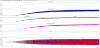
png file plot shows from top to bottom :
-Field losses
-net ouput (load) power - in watts, (do not be confused by the units legend)
-DC voltage (after rectifier / smoother)
-electrical power of the generator derived from electrical torque
-rotor (mechanical) speed in turns/s
-abc phase voltage waveforms
Since the png alone won't help much, the model is available there and there is more info :
it is a zip file with the png, asc, plt, net and readme file.
https://www.skynext.tech/index.php/...awt-prime-mover-and-dc-battery-charging-load/
The model in the article does not include the VAWT prime mover, as it is not relevant for the immediate issues, but a ramped up mechanical input power, and that way the simulation is faster.
Please check the readme in the archive. ltspice needs to be 17.1.5 at least and the solver set to alternate.
So, there are basically two types of models : abc reference frame models aka phase variable models and dq0 reference models.
dq0 are primarily used for steady state modelling of generators coupled to the grid.
On the other hand, abc reference frame models seem better suited for non steady state, autonomous power generation (islanded) modes, but at the expense of simulation performance.
Since I wish to model a generator coupled to a prime mover like a VAWT (vertical axis wind turbine) under time varying wind conditions, abc modelling seems a better choice.
So, I've made a model under Ltspice. it works, but now i need to plug in 'natural' inductances for a physically realisable generator, or better, for a commercially available generator :
The main issues and important points being :
- Abc reference frame example inductance data is hard to come by. just found one paper from 1976 and a more recent one that proposes a method to derive inductance data in natural reference frame from dq0 data available in most datasheets.
- It seems that not all inductance parameters in abc reference frame can be derived from the dq0 reference frame through inverse Park transform, or else the above paper would not be a thing. Some inductance parameter components can be derived from Ldm and Lqm as seen in chapter 5 of Ion Boldea book on synchronous generators
- Experimental measurements of all natural inductance components (to get rough estimates) - leakage and mutual, except for dampers, might be done if one has access to a all stator winding leads and neutral, as well as the excitation winding (assuming a brushed alternator), by using open circuit + short circuit measurements as one would do with coupled inductors, and under various rotor positions : https://electronics.stackexchange.c...lient-rotor-inductances-and-resistances-measu (1)
- There is a great variance in simulation speeds based on the inductances supplied to the model : using the parameters from the 1976 paper that follows yields very slow simulation speeds in the µs/s range vs using the recent paper with ranges in the hundreds of ms/s : What I observed is that the higher the coupling coefficient between windings - ratio of mutual inductance to square root of self inductances products - the slower it gets. https://ttu-ir.tdl.org/bitstream/handle/2346/15506/31295015505711.pdf?sequence=1 (2)
- Using the values from the paper https://studylib.net/doc/18754307/analysis-of-synchronous-machine-modeling-for-simulation-and (3) is fast, but gives large ohmic losses in the field winding compared to output power for various field voltage configurations as well as load impedances. Never below 10%. Based on litterature, field losses should account no more than 2%. I am not sure if the "natural" inductances specified in (3) are equivalent to the abc reference frame inductances I am looking for, as it seems that the order of magnitude of inductances in that paper is really high for a 75kva alternator... which could explain why the model shows poor efficiency.
My main question are, is that modelling approach a dead end ? That is, simulating a proper generator in the abc reference frame will be often to slow to reasonably simulate the behaviour of an efficient and physically realisable generator for time periods of several seconds to minutes ?
Any idea on where to find natural inductances in the litterature, or those from experimental measurements ? - I searched everywhere - and finally Is the methodology for measuring inductances in the link (1) valid ?
Notes : as for the model, I took care to review reputable sources to translate it to Ltspice. (mostly Ion Boldea synchronous generator handbook and the Sauer and Pai book). The model is based on arbitrary inductor Ltspice modelling with flux expressions. It uses the most commonly agreed upon conventions :
All inductance terms are positively valued, and all total flux sums use positive terms. Adequate current measurement vectors for the stator (leaving the stator) are obtained by rotating the inductor (see phase dots).
But there could be errors or oversights... any input much appreciated !
I am working on standardizing the inductance variable and parameter names to follow one reference book (will probably settle for Ion Boldea's book), for now it is still a mixed bag :(
png file plot shows from top to bottom :
-Field losses
-net ouput (load) power - in watts, (do not be confused by the units legend)
-DC voltage (after rectifier / smoother)
-electrical power of the generator derived from electrical torque
-rotor (mechanical) speed in turns/s
-abc phase voltage waveforms
Since the png alone won't help much, the model is available there and there is more info :
it is a zip file with the png, asc, plt, net and readme file.
https://www.skynext.tech/index.php/...awt-prime-mover-and-dc-battery-charging-load/
The model in the article does not include the VAWT prime mover, as it is not relevant for the immediate issues, but a ramped up mechanical input power, and that way the simulation is faster.
Please check the readme in the archive. ltspice needs to be 17.1.5 at least and the solver set to alternate.