- #1
MermaidWonders
- 112
- 0
View attachment 7919
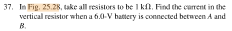
I tried redrawing the above circuit so that it resembles more like the circuit diagrams we see from day to day. However, what confused me was when it asks for the resistance measured between A and B versus between A and C What's the difference between those two, and how would the calculations differ in each case?
I tried redrawing the above circuit so that it resembles more like the circuit diagrams we see from day to day. However, what confused me was when it asks for the resistance measured between A and B versus between A and C What's the difference between those two, and how would the calculations differ in each case?
Attachments

Last edited: