How do I fix the signs in Faraday's Law in RL Circuit?

  • Thread starter zenterix
  • Start date
  • Tags
    Rl circuit
  • #1
zenterix
488
71
Homework Statement
I am having major issues getting around calculations of
Relevant Equations
$$\oint\vec{E}\cdot d\vec{l}=-L\dot{I}

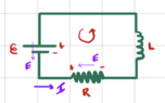
Consider the circuit below.
1713024386897.png

Just from looking at this circuit, we would expect the positive current to flow in a clockwise direction.

Let's define the normal vector pointing out of the screen. Then the positive circulation direction is counterclockwise.

I think that means that we have

1713024511072.png


I am not sure about the following: when we define the positive circulation direction we decide the direction that we are setting the positive ##I## to.

Consider the integral

$$\mathcal{E}_L=\oint\vec{E}\cdot d\vec{l}\tag{1}$$

It seems that we have

$$\oint\vec{E}\cdot d\vec{l}=\mathcal{E} -IR=-L\dot{I}\tag{2}$$

$$\dot{I}-\frac{R}{L}I=-\frac{\mathcal{E}}{L}\tag{3}$$

This doesn't seem correct, however.

After all, it leads to the solution

$$I(t)=\frac{\mathcal{E}}{R}\left (1-e^{\frac{Rt}{L}}\right )\tag{4}$$

But then ##I## starts at zero and then grows in magnitude without bounds. The sign is negative so the current does flow clockwise as we would expect.

I think the issue is the sign on the rhs of (2), ie the sign on ##-L\dot{I}##. I'd like to be able to explain why it should not have the negative sign.

If I do the calculation for current in the other direction it comes out right.

1713025558784.png


$$-\mathcal{E}+IR=-L\dot{I}$$

$$\dot{I}+\frac{R}{L}I=\mathcal{E}$$

I am missing something in going from this calculation to the one before.
 
Physics news on Phys.org
  • #2
Here is another attempt to express what I am trying to ask.

Let me write the inductor as a one-loop inductor.

1713028936185.png


We define the normal unit vector as pointing into the screen.

From the direction of the current through the inductor, we will get a magnetic field pointing into the screen.

The flux through the inductor is thus positive. If ##\dot{I}>0## then the inductor will behave like a battery with back emf as depicted on the right picture above.

$$\oint\vec{E}\cdot d\vec{l}=-\mathcal{E}+|\mathcal{E}_L|+IR=0$$

$$|\mathcal{E}_L|+IR=\mathcal{E}$$

$$L\dot{I}+IR=\mathcal{E}$$

I put the absolute value in there because that is what I think makes sense in terms of the physics: if we think of the inductor as behaving like a battery then as we pass over it in the line integral we are moving with the electric field inside of it and so ##\int\vec{E}\cdot d\vec{l}## inside that fictitious battery should be positive.

But this seems hacky. I am trying to figure out a more systematic way to think about this.
 
  • #3
zenterix said:
But this seems hacky. I am trying to figure out a more systematic way to think about this.

The basic physics is Faraday's law: $$\oint\vec{E}\cdot d\vec{l} = -\frac{d\Phi}{dt}$$
Apply this to the LR circuit shown:
1713047162800.png

Choose a direction for the line integral ##\oint\vec{E}\cdot d\vec{l}##. We could choose clockwise or counterclockwise. Let's choose clockwise as shown by the dotted arrows on the diagram. The line integral goes around the circuit loop and stays within the helical winding of the inductor. If the inductor has negligible resistance, there will be negligible electric field within the winding of the inductor. So, only the line integral of ##\vec E## through the battery and the resistor will contribute to the left side of Faraday's law. For the battery, ##\int_{bat}\vec{E}\cdot d\vec{l} = -\mathcal{E}##.

For the resistor, we need to choose the direction of positive current ##I##. We could choose clockwise current as positive or counterclockwise current as positive. Let's choose the positive direction of current to be clockwise. So, the dotted arrows represent our choice of direction of integration and also our choice of positive current. With this choice, ##\int_{Res}\vec{E}\cdot d\vec{l} =+IR##.

So, the left side of Faraday's law reduces to $$\oint\vec{E}\cdot d\vec{l} = -\mathcal{E} + IR.$$
The right side of Faraday's law represents the rate of change of the total magnetic flux through the path of integration chosen for the left side of Faraday's law. The sign of the flux is determined by a right-hand rule. If you curl the fingers of your right hand around the the circuit in the direction you chose for the path of integration of ##\vec E##, your thumb will point in the direction of positive flux. For example, consider your one-loop circuit:
1713050662286.png

If you choose the direction of integration of ##\oint\vec{E}\cdot d\vec{l}## on the left side of Faraday's law to be clockwise, then the direction of positive flux ##\Phi## appearing on the right side of Faraday's law will be into the page as you indicated.

For the multi-turn coil shown in the diagram above, curl the fingers of your right hand around the coil in the direction of the dotted arrows. Positive direction of flux is in the direction of your thumb, which is downward. Since the positive current direction was chosen to be in the direction of the dotted arrows, you can see that positive current produces positive flux. So, we would write ##\Phi = + LI## and the right-hand side of Faraday's law reduces to ##-L\dot I##. You can easily check that the right-hand side would still be ##-L\dot I## if the windings of the coil were in the opposite sense:

1713052635045.png

Here, we still assume the dotted arrows are in the same direction through the battery and resisitor. For the circuit on the right, positive flux will be upward in the coil. But that's the direction of flux that positive current will produce.

Thus, for our choice of the direction of integration of ##\oint\vec{E}\cdot d\vec{l}## and our choice of the positive direction for ##I##, Faraday's law reduces to $$-\mathcal{E} + IR = -L\dot I$$ Or, $$L\dot I + IR = \mathcal{E}. $$
If we had chosen the positive direction of current to be counterclockwise while keeping the direction of integration of ##\vec E## clockwise, the terms ##L\dot I## and ##IR## would change sign.
 
  • Like
Likes hutchphd
  • #4
TSny said:
If we had chosen the positive direction of current to be counterclockwise
I understand the concepts and general calculations but I was hoping precisely to see the calculations for the opposite choice of normal vector and opposite choice of circulation direction. The main issue I have is why do we switch the sign of the term ##-L\dot{I}##?

Suppose we choose the normal vector pointing out of the page of your diagrams, thus defining positive circulation direction as counterclockwise.

For the solenoid on the left, the normal vector points up, and for the solenoid on the right the normal vector points down. These directions coincide with the respective magnetic fields inside each solenoid for positive current and so positive current generates positive magnetic flux.

Still we have ##\mathcal{E}_L=-L\dot{I}## and

$$\mathcal{E}+IR=-L\dot{I}$$

$$\dot{I}+\frac{R}{L}I=-\mathcal{E}$$

The solution to which is

$$I(T)=-\frac{\mathcal{E}}{R}\left (1-e^{-\frac{Rt}{L}}\right )$$

which is the same solution we obtain when we define the circulation direction pointing into the screen.

Note that the current starts at zero and grows in magnitude to ##\mathcal{E}/R## but has a negative sign.

At this point I realize that the main issue I had up to this point in my calculations was in the calculation of ##\int_{resistor}\vec{E}\cdot d\vec{l}##.

Considering the counterclockwise circulation direction (and integration direction), even though we are moving against the electric field, Ohm's law is such that

$$\int\vec{E}\cdot d\vec{l}=V_{initial}-V_{final}=IR$$

where ##V_{initial}## and ##V_{final}## are the potentials when we enter and exit the resistor, and ##I## is the current going into the resistor.

This is why we use plus ##IR## and not negative ##IR## even though in the end we discover that in fact, since ##I## is negative, the integral ##\int_{resistor}\vec{E}\cdot d\vec{I}=IR## is negative.

I just realized you wrote the following

TSny said:
while keeping the direction of integration of E→ clockwise

I thought the circulation direction obtained relative to choice of normal vector determined the direction of evaluation of this line integral.

If we are integrating clockwise then we are going against the right-hand rule circulation direction.

Recall that the negative sign in ##\mathcal{E}_L=\oint\vec{E}\cdot d\vec{l}=-L\dot{I}=-\dot{\Phi}## is from Lenz's law. If we pick circulation direction to coincide with right-hand rule then, as far as I can see, 1) positive current generates positive flux, 2) ##\dot{I}>0## generates induced current opposite the original current which is why 3) ##\mathcal{E}_L=-L\dot{I}##, which means the work (per unit charge) by the induced electric field (along the direction of circulation) is negative.

If, as you suggest, we define counterclockwise circulation direction but nonetheless do the line integral clockwise, then it seems to me that in ##\mathcal{E}_L=\oint\vec{E}\cdot d\vec{l}=-L\dot{I}=-\dot{\Phi}## what changes is the sign on the line integral ##\oint\vec{E}\cdot d\vec{l}##.

What happens seems to be that

$$-\mathcal{E}_{L,opp}=-\oint_{opp}\vec{E}\cdot d\vec{l}=\oint\vec{E}\cdot d\vec{l}=-L\dot{I}=-\dot{\Phi}$$

$$\mathcal{E}_{L,opp}=L\dot{I}=\dot{\Phi}$$

Notice that ##\oint_{opp}\vec{E}\cdot d\vec{l}## is now the line integral in the opposite direction to the positive current circulation direction and that ##\mathcal{E}_{L,opp}## equals this new line integral. We have effectively redefined the back emf as the integral of the induced electric field in the direction opposite to the circulation direction, and this back emf has the relationship

$$\mathcal{E}_{L,opp}=-\mathcal{E}_L=L\dot{I}$$

The physical interpretation here is that the work (per unit charge) done by the induced electric field against the current circulation direction is positive, which makes sense since the back emf opposes the current.
 
Last edited:
  • #5
With this new ##\mathcal{E}_{L,opp}## we have

$$\mathcal{E}_{L,opp}=\oint_{opp}\vec{E}\cdot d\vec{l}=-\oint\vec{E}\cdot d\vec{l}=-(\mathcal{E}+IR)=-\mathcal{E}-IR=L\dot{I}$$

$$\dot{I}+\frac{R}{L}I=-\frac{\mathcal{E}}{L}$$

which gives us the correct solution: a negative ##I## (which means clockwise current, even though we chose counterclockwise positive current) that starts at zero and goes to ##-\mathcal{E}/R##.
 
Last edited:
  • #6
At this point I think I have solved many of my doubts. In this post I will summarize everything.

Consider the following RL circuit

1713082660472.png


The first thing we do is define a direction for the normal vector to the enclosed surface. This will define the right-hand rule (rhr) circulation direction for which current is positive.

We have two choices: into the screen or out of the screen.

Ultimately, we would like to apply Faraday's law and obtain an equation for the current as a function of time.

$$\mathcal{E}_L=\oint\vec{E}\cdot d\vec{l}=-L\dot{I}=-\dot{\Phi}\tag{1}$$

Note
(1) involves a line integral and the negative of a rate of change of a surface integral.

This relationship, as it is written, contains implicit assumptions about how to compute the line integral and surface integral.

In particular, such assumptions make the signs come out right.

(1) is correct if we define positive current to flow in the direction determined by the rhr (given our choice of normal vector)

If we do this, then the relationship between magnetic flux and current in an inductor is given by


$$\Phi=LI$$

$$\dot{\Phi}=L\dot{I}$$

with ##L>0##.

Here is a picture to try to show why this is

1713083259846.png


Note that the coils are wound differently in the two cases above (and just to be perfectly clear, as we follow the coil from left to right the first loop is such that the rightmost side of that loop is nearer to the reader, and the leftmost side is nearer to the computer screen; you can also reach this conclusion by comparing the little arrows denoting current to the direction of the ##B## field line I drew in).

Suppose that in both cases ##\dot{I}>0##.

Then, for both cases the following relationships hold

$$\dot{I}>0$$

$$\Phi>0$$

$$\dot{\Phi}>0$$

$$\mathcal{E}_L=-L\dot{I}<0$$

What this all means is that when we have an inductor in a circuit, as we have below, as long as we follow the recipe of computing the line integral in the rhr positive circulation direction and also defining positive current in this direction, then we do in fact have the relationship in (1).

Case 1: ##\hat{n}_{rhr}## points into the screen ##\implies ## clockwise positive circulation direction.

1713082881601.png


When I asked my original questions in the OP, I knew most of what I wrote above (though perhaps not in an organized way in my mind as I am trying to do with this summary). What I got wrong was the part I will do now, which is to compute ##\oint\vec{E}\cdot d\vec{l}## correctly.

Let's consider this line integral in parts. Remember that we will do it in the positive direction of circulation, which in this case is clockwise.

Battery
$$\int_{batt}\vec{E}\cdot d\vec{l}=\int_-^+\vec{E}\cdot d\vec{l}$$

$$=\int_-^+(-\vec{f}_s)\cdot d\vec{l}$$

$$=-\mathcal{E}$$

where I have used the definition of electromotive force of a chemical battery ##\mathcal{E}=\int_-^+ \vec{f}_s\cdot d\vec{l}##.

##\vec{f}_s## is the "source force" inside the battery, and ##\vec{f}_s+\vec{E}=0\implies \vec{E}=-\vec{f}_s## inside the battery.

Resistor (this is the thing I was getting wrong, mostly)
$$\int_R \vec{E}\cdot d\vec{l} = -\Delta V_R = V_+-V_-=IR$$

In words, the integral of electric field across the resistor (where across means across in the direction of positive circulation) equals the negative of the potential difference across the resistor, which is simply the potential when you enter the resistor minus the potential when you exit the resistor. By Ohm's law, this is just ##IR##.

Note that the important and subtle point here is that to get the sign right you need to write Ohm's law given your choice of direction for $I$. Since the current is just ##I## in the direction required in Ohm's law then we get just ##IR##.

Inductor
$$\int_{ind}\vec{E}\cdot d\vec{l}=0$$

Faraday's Law

$$\mathcal{E}_L=\oint\vec{E}\cdot d\vec{l}=-\mathcal{E}+IR=-L\dot{I}$$

$$\dot{I}+\frac{R}{L}I=\frac{\mathcal{E}}{L}$$

$$\implies I(t)=\frac{\epsilon}{R}\left (1-e^{-\frac{Rt}{L}}\right )$$

Now let's consider the case in which we define the normal vector to be pointing out of the screen.

Case 2: ##\hat{n}_{rhr}## points out of the screen ##\implies ## counterclockwise positive circulation direction.

1713087476313.png


Battery

$$\int_{batt}\vec{E}\cdot d\vec{l}=\int_+^- \vec{E}\cdot d\vec{l}$$

$$=-\int_-^+\vec{E}\cdot d\vec{l}$$

$$=-\int_-^+(-\vec{f}_s)\cdot d\vec{l}$$

$$=\int_-^+\vec{f}_s\cdot d\vec{l}$$

$$=\mathcal{E}$$

Resistor
$$\int_R \vec{E}\cdot d\vec{l} = -\Delta V_R=V_+-V_-=IR$$

Inductor
$$\int_{ind} \vec{E}\cdot d\vec{l}=0$$

Faraday's Law
$$\mathcal{E}_L=\oint \vec{E}\cdot d\vec{l}=\mathcal{E}+IR=-L\dot{I}$$

$$\dot{I}+\frac{R}{L}I=-\frac{\epsilon}{L}$$

$$\implies I(t)=-\frac{\epsilon}{R}\left (1-e^{-\frac{Rt}{L}}\right )$$

This result is essentially the same one we got in case 1. The negative sign in front just means that current is flowing in the opposite direction to what we defined as the positive direction. Since positive in this case is counterclockwise then negative is clockwise. Current flows clockwise.

Note that in case 1 we defined positive as clockwise and the current came out positive so it also flowed clockwise.

Note

Up to this point all we did was do the calculations present in Faraday's law as it is usually stated.

We did not have to change any signs or anything.

What Happens If We Don't Use Right-Hand Rule?

Suppose that we are in case 1 and we choose ##I## as having counterclockwise direction instead of clockwise.

Then we would have

$$\int_R \vec{E}\cdot d\vec{l} = -\Delta V_R = V_+-V_-=(-I)R$$

Note that the only thing that changed was in the rightmost term where we now have ##-I## where before we had just ##I##.

Nothing would change for the calculation involving the battery.

But now let's think about the inductor.

1713086261358.png


For these inductors the following relationships hold

Assuming ##I>0##, ##\dot{I}>0##, and ##L>0## we have

$$\Phi<0$$

$$\dot{\Phi}<0$$

$$\Phi=-LI$$

$$\dot{\Phi}=-L\dot{I}$$

$$\mathcal{E}=L\dot{I}$$

Therefore, Faraday's law applied to the circuit becomes

$$-\mathcal{E}-IR=L\dot{I}$$

$$\dot{I}+\frac{R}{L}I=-\mathcal{E}$$

Which is the same differential equation we got in case 2 (even though we are considering case 1 here). All this means is that the solution is a current that changes from ##0## to ##-\mathcal{E}/R##. That is, it is always negative which means it flows clockwise.

Finally, let's consider case 2 (counterclockwise positive circulation) but supposing we have a positive ##I## in the clockwise direction.

We still have ##\int_{batt}\vec{E}\cdot d\vec{l}=\mathcal{E}##.

$$\int_{R}\vec{E}\cdot d\vec{l}=V_+-V_-=(-I)R$$

And by the same reasoning we showed just a bit above, Faraday's law becomes $$\mathcal{E}=L\dot{I}$$

That is, we removed the negative sign since for this configuration of circulation direction and choice of current direction, the relationship between magnetic flux and current is now ##\Phi=-LI##.

Faraday's law applied to the circuit is then

$$\mathcal{E}-IR=L\dot{I}$$

$$\dot{I}+\frac{R}{L}I=\mathcal{E}$$

Final Note

There is still one more weird (not recommended) thing one can do. I will only mention it here since I talked about it in the second half of post #4 in this thread.

Suppose you decided on a normal vector, you have your rhr positive circulation direction, and you pick your positive current to be in this same direction. If you now do the line integral ##\oint\vec{E}\cdot d\vec{l}## in the direction opposite that of the positive rhr direction, then you will have to use ##L\dot{I}## instead of ##-L\dot{I}## in Faraday's law.

The lesson here is that one should use the right-hand rule to dictate everything. No one wants to be searching for signs in calculations. I just did this for a large number of hours to be able to write this post and it's not fun, though it is enlightening in the end.
 

Attachments

  • 1713084798739.png
    1713084798739.png
    8.4 KB · Views: 2
Last edited:
  • Like
Likes TSny

Similar threads

  • Introductory Physics Homework Help
Replies
1
Views
133
  • Introductory Physics Homework Help
Replies
7
Views
95
  • Introductory Physics Homework Help
Replies
6
Views
105
  • Introductory Physics Homework Help
Replies
2
Views
202
  • Introductory Physics Homework Help
Replies
3
Views
161
  • Introductory Physics Homework Help
Replies
1
Views
148
  • Introductory Physics Homework Help
Replies
1
Views
166
  • Introductory Physics Homework Help
Replies
2
Views
812
  • Introductory Physics Homework Help
Replies
7
Views
80
  • Introductory Physics Homework Help
Replies
6
Views
306
Back
Top